Time Domain Reflectometry (TDR) calibration is the foundation of accurate impedance control PCB measurement for high-speed designs. Without proper calibration, even the best PCB stackup will fail signal integrity tests. This guide covers the complete workflow to calibrate TDR for precise impedance control PCB measurement, ensuring repeatable results for 50-ohm or differential pairs.
1. Why Calibrate TDR for Impedance Control PCB Measurement
Calibrate TDR for impedance control PCB measurement to remove systematic errors from cables, connectors, and internal circuitry. A raw TDR reading includes cable loss and parasitic inductance. Calibration establishes a known reference plane at the probe tip, enabling accurate impedance control PCB measurement of traces.
1.1 Open, Short, Load Standards
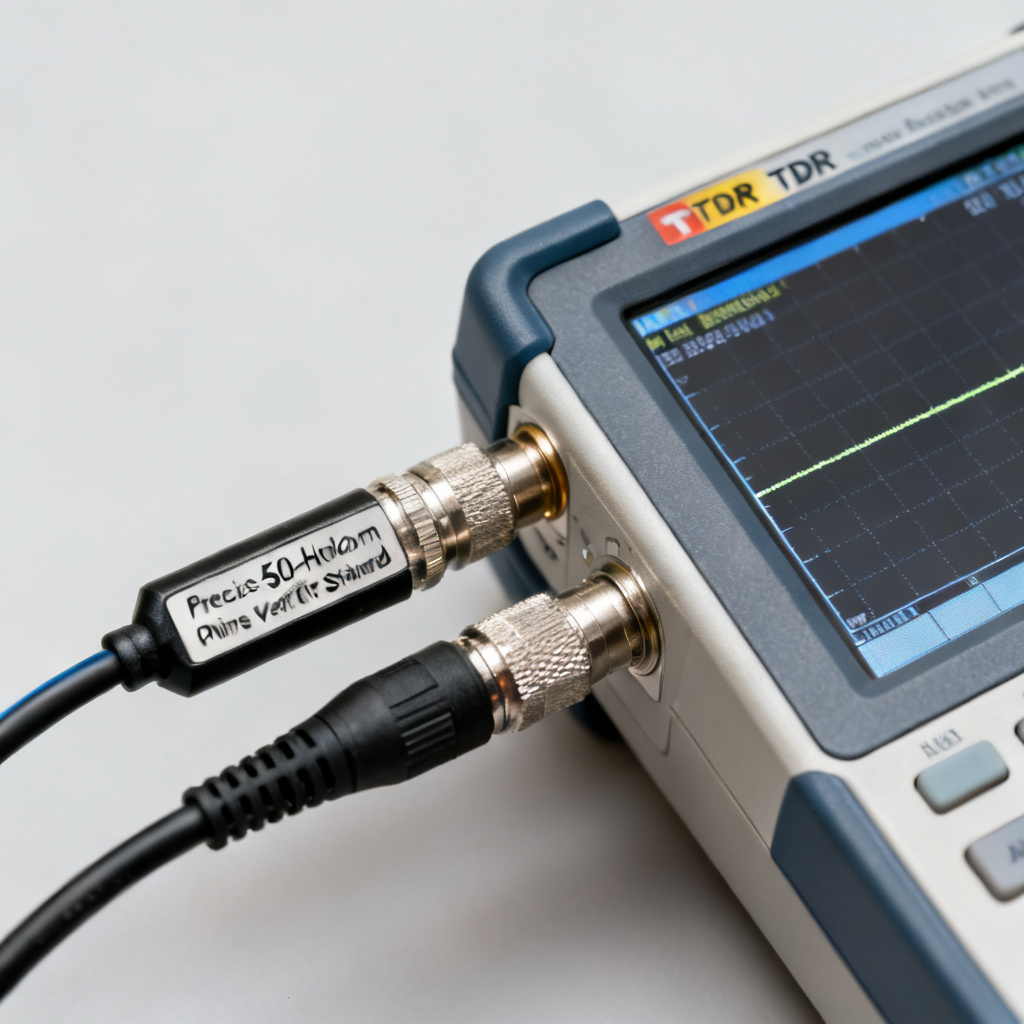
The OSL method uses three standards: open (infinite impedance), short (zero impedance), and load (50 ohms). Each corrects a specific error term. For impedance control PCB measurement, the load must be a precision 50.0-ohm resistor. This step is critical to calibrate TDR correctly.
1.2 Reference Plane Definition
The reference plane is the physical point where measurement begins. For PCB probing, this is at the probe tip or SMA connector. Proper calibration defines this plane, making subsequent impedance control PCB measurement independent of cable length.
1.3 Impact on Impedance Tolerances
PCB impedance tolerances are often ±10% or tighter (e.g., 50Ω ±5%). A 0.5-ohm error from uncalibrated cable loss can cause false pass/fail decisions. Therefore, you must calibrate TDR to verify impedance control PCB measurement within specification.
2. Step-by-Step TDR Calibration for Impedance Control PCB Measurement
Perform these steps in a stable environment (23°C ±2°C) after a 30-minute warm-up. This procedure ensures your calibrate TDR routine is repeatable for every impedance control PCB measurement.
2.1 Connect Calibration Kit
Attach the open, short, and load standards to the test cable. Use a precision kit (e.g., Tektronix 067-0151-00 or Keysight 85052D). Clean all connectors with isopropyl alcohol before each impedance control PCB measurement session.
2.2 Set TDR Parameters
Set rise time to fastest (e.g., 25 ps), time base to capture reflection (e.g., 20 ns for 1-meter cable), and averaging to 16 or 64. Do not use averaging during calibration if the algorithm expects single-shot data. This optimizes the calibrate TDR process.
2.3 Measure Open Standard
Attach the open standard. The TDR should show +1 reflection coefficient. If not flat, adjust the open calibration coefficient. Some instruments allow a “null” button. This step is essential for impedance control PCB measurement accuracy.
2.4 Measure Short Standard
Replace with short standard. Expect -1 reflection coefficient. Check contact quality; clean if ringing appears. This corrects parasitic inductance for subsequent impedance control PCB measurement.
2.5 Measure Load Standard
Attach 50-ohm load. The TDR should show zero reflection. Any deviation indicates load mismatch or cable loss. The instrument computes error terms from these three measurements to calibrate TDR fully.
2.6 Compute Calibration Coefficients
The firmware solves for directivity, source match, and reflection tracking. After completion, you see “Calibration Complete.” Now your TDR is ready for accurate impedance control PCB measurement.
2.7 Verify Calibration
Attach a known verification standard (e.g., 50-ohm airline). Measured impedance should be within ±0.5%. If not, repeat the calibration. This verification is the final step to calibrate TDR reliably.
3. Advanced Techniques to Calibrate TDR for Impedance Control PCB Measurement
For 10 Gbps and above, basic OSL calibration may not suffice. These advanced methods ensure your calibrate TDR routine handles high-speed impedance control PCB measurement.
3.1 De-Embedding Probes and Fixtures
Probe ground springs add parasitic inductance. Use a through calibration on a known substrate (e.g., 50-ohm CPW line) to de-embed the probe. This improves impedance control PCB measurement accuracy for fine-pitch traces.
3.2 Cable Loss Compensation
Long cables cause frequency-dependent attenuation. Use low-loss semi-rigid cables (e.g., Gore) or enter cable loss at 1 GHz in the TDR menu. Compensating cable loss is vital to calibrate TDR for long test setups.
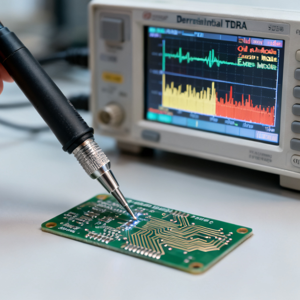
3.3 Differential TDR Calibration
For differential pairs (e.g., 100 ohms), calibrate odd-mode and even-mode impedances. Use a differential load or combine two single-ended calibrations. Ensure cables are length-matched within 1 ps for accurate impedance control PCB measurement.
3.4 Temperature and Time Stability
Recalibrate every 2 hours or if temperature changes by more than 2°C. Use a calibration check (e.g., 50-ohm load) at shift start. This maintains the integrity of your calibrate TDR process.
4. Common Errors When Calibrating TDR for Impedance Control PCB Measurement
Even experienced engineers encounter issues. Here are solutions to ensure your calibrate TDR routine is error-free for impedance control PCB measurement.
4.1 Ringing on Open or Short
Cause: Poor connector contact or worn standards. Solution: Clean connectors and use torque wrench (8 in-lbs for SMA). Replace standards if ringing persists.
4.2 Load Shows Non-Zero Reflection
Cause: Load not exactly 50 ohms or cable loss. Solution: Verify load DC resistance with multimeter (50.0 ohms ±0.1). Apply cable loss compensation.
4.3 Calibration Fails to Converge
Cause: Time base too short. Solution: Increase time base to capture full reflection from open and short. Ensure standards are at cable end.
4.4 Impedance Drifts After Calibration
Cause: Temperature changes or warm-up drift. Solution: Allow 30-minute warm-up. Recalibrate if ambient temperature changes. Use temperature-controlled chamber for critical impedance control PCB measurement.
5. Best Practices for Impedance Control PCB Measurement After Calibration
Once you calibrate TDR, apply these practices for reliable impedance control PCB measurement.
5.1 Use Consistent Test Coupon
Measure on a coupon replicating production stackup and trace geometry. Include same prepreg, core, and copper weight. Place at panel edge to avoid warpage.
5.2 Measure at Multiple Points
Take at least three measurements (beginning, middle, end) to capture variation due to etching and glass weave. Record average and standard deviation for impedance control PCB measurement.
5.3 Compare with Simulation
Simulate expected impedance using field solver (e.g., Ansys Q3D). Compare with TDR result. Discrepancy >2 ohms indicates calibration error or stackup mismatch.
5.4 Document Calibration
Record calibration date, standards, cable type, and temperature. This traceability is essential for ISO 9001 compliance in impedance control PCB measurement.
| Parameter | Value | Impact on Impedance Control PCB Measurement |
|---|---|---|
| Rise Time | 25 ps | Defines spatial resolution for trace length |
| Time Base | 20 ns (1m cable) | Captures full reflection from standards |
| Averaging | 16–64 | Reduces noise, improves repeatability |
| Load Resistance | 50.0 Ω ±0.1% | Sets baseline impedance scaling |
| Temperature | 23°C ±2°C | Minimizes drift in measurement |
FAQ: How to Calibrate TDR for Impedance Control PCB Measurement
Q: How often should I calibrate TDR for impedance control PCB measurement?
A: Recalibrate every 2 hours or if temperature changes by more than 2°C. For production, use a calibration check at shift start.
Q: What is the best method to calibrate TDR for differential impedance control PCB measurement?
A: Use a differential load standard or combine two single-ended calibrations. Ensure cables are length-matched within 1 ps.
Q: Can I calibrate TDR without a calibration kit?
A: No, a precision OSL kit is required for accurate impedance control PCB measurement. Improvised standards introduce errors.
Q: Why does my impedance control PCB measurement drift after calibration?
A: Drift is usually due to temperature changes or incomplete warm-up. Allow 30-minute warm-up and maintain stable environment.