[rank_math_breadcrumb]
In high-speed PCB design, accurately measuring differential pair impedance using TDR with true differential mode is critical for signal integrity in protocols like USB, HDMI, PCIe, and Ethernet. This guide covers equipment, calibration, and interpretation for reliable results.
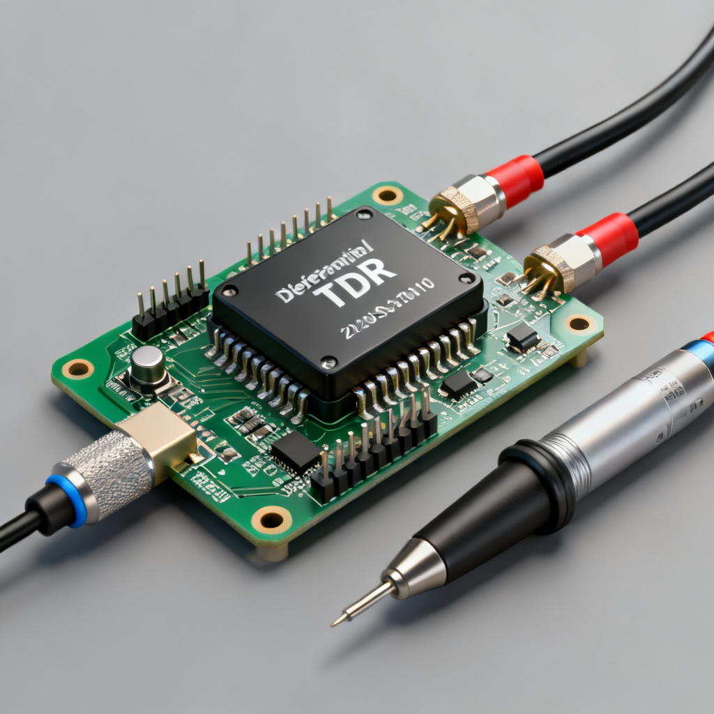
Image: 
1. Understanding Differential Pair Impedance and TDR Fundamentals
1.1 What is Differential Impedance?
Differential pair impedance (Z_diff) is measured between two conductors driven by a differential signal. For a coupled pair, Z_diff = 2 × Z_se × (1 – k), where k is the coupling coefficient. Typical targets are 100Ω or 85Ω for high-speed PCBs.
1.2 What is TDR and How Does It Work?
TDR sends a fast-rise-time step pulse down a transmission line and measures reflections. The reflection coefficient ρ = (Z_line – Z_reference) / (Z_line + Z_reference) provides an impedance vs. distance profile.
1.3 Single-Ended vs. Differential TDR
Single-ended TDR measures each trace separately and mathematically computes Z_diff, assuming no coupling. True differential TDR uses two synchronized sources to directly measure differential impedance, accounting for coupling and skew.
2. Equipment and Setup for True Differential Mode TDR
2.1 Required Equipment
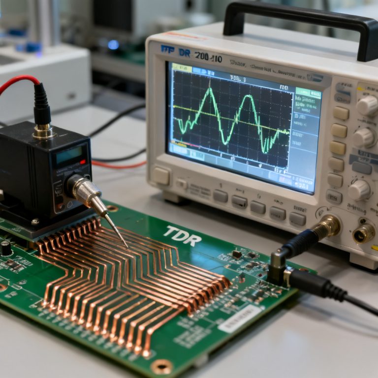
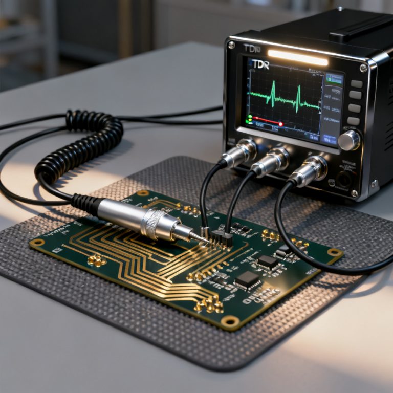
To measure differential pair impedance accurately, you need: a differential TDR module (e.g., Tektronix DSA8300), matched coaxial cables, differential probes, calibration standards, and TDR analysis software.
| Equipment | Purpose for Differential Pair Impedance Measurement |
|---|---|
| Differential TDR Module | Generates and measures differential signals |
| Matched Cables | Minimize skew and phase mismatch |
| Differential Probes | Contact PCB pads with low inductance |
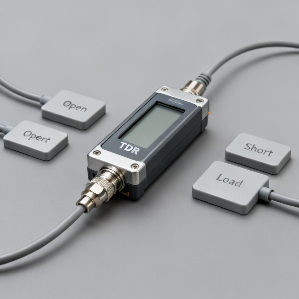
| Calibration Standards | Open, short, load, and differential reference |
2.2 Probe Selection and Connection
Use differential probes with short ground tips (<2 mm) to minimize inductance. For production, use SMA connectors with phase-stable cables.
2.3 Environmental Considerations
Maintain stable temperature (20-25°C) and ensure solid grounding to avoid measurement errors in differential pair impedance.
3. Step-by-Step Measurement Procedure
3.1 Step 1: Calibrate the TDR System
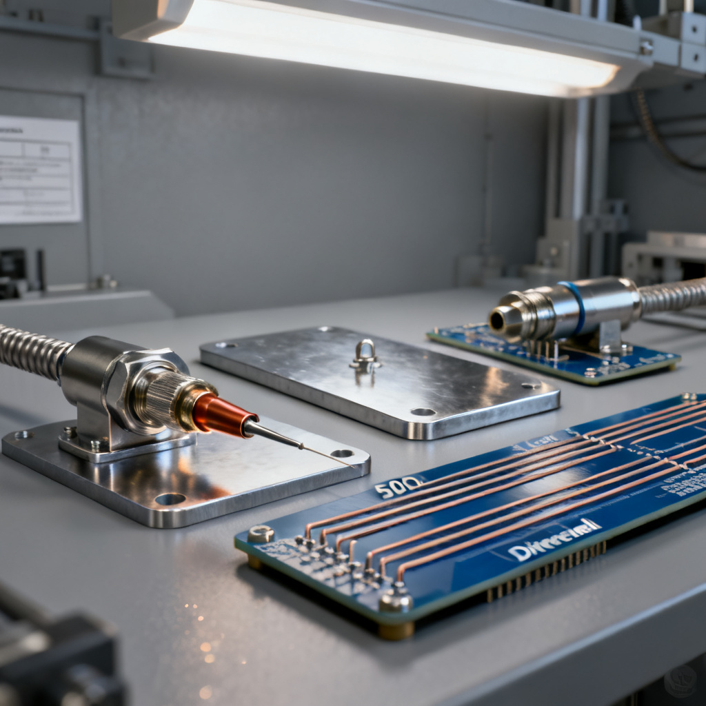
In compliance with differential pair routing rules, perform a full differential calibration including open, short, load, and skew calibration. This is essential for accurate differential pair impedance measurement.
3.2 Step 2: Connect to the DUT
Connect to test pads or SMA connectors on the PCB. Ensure clean contacts and use a microscope for probe alignment.
3.3 Step 3: Configure the TDR Settings
Set rise time (35-100 ps), time window (trace length + 20%), averaging (16-64), and impedance scale centered on target.
3.4 Step 4: Acquire the Waveform
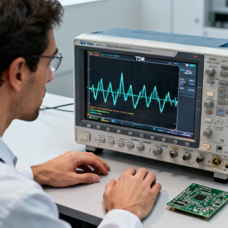
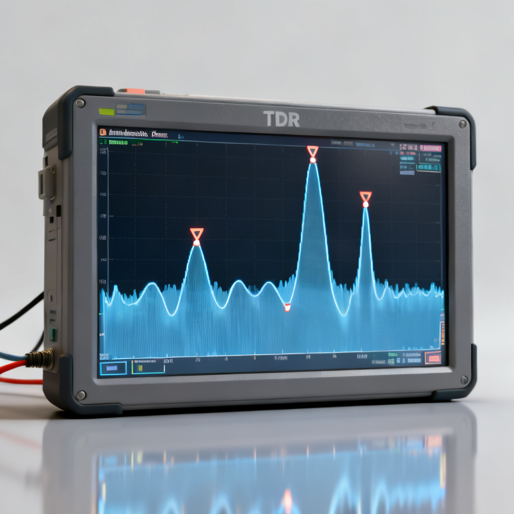
Acquire the waveform and observe the impedance vs. distance plot. Look for a flat region indicating consistent differential pair impedance.
3.5 Step 5: Interpret the Results
Measure average impedance (e.g., 100Ω ±10%) and identify discontinuities. Use cursor tools for precise analysis.
3.6 Step 6: De-embedding (Advanced)
Use time-domain or frequency-domain de-embedding to remove probe and cable effects for on-board measurements.
4. Common Pitfalls and How to Avoid Them
4.1 Incorrect Calibration
Always perform full differential calibration. Single-ended calibration alone leads to errors in differential pair impedance.
4.2 Probe Inductance
Use short ground tips (<2 mm) to avoid false impedance peaks.
4.3 Cable Skew
Use matched-length, phase-stable cables and calibrate out residual skew.
4.4 Poor Contact
Clean pads with isopropyl alcohol and use probe positioners.
4.5 Incorrect Velocity of Propagation (Vp)
Measure actual Vp using a known trace length to ensure accurate distance conversion.
4.6 Mode Conversion (SCD21, SCD11)
Analyze common-mode reflections to detect asymmetry that can cause EMI.
5. Advanced Techniques for High-Speed PCB Validation
5.1 Statistical Analysis for Production Testing
Use SPC charts on multiple boards to ensure differential pair impedance stays within specification (e.g., 100Ω ±5Ω).
5.2 Frequency-Domain Correlation
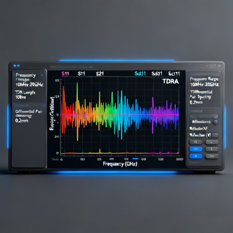
Convert TDR data to frequency domain to obtain insertion loss (SDD21) and return loss (SDD11).
5.3 Eye Diagram from TDR
Reconstruct eye diagrams from impedance profiles for visual signal quality assessment.
5.4 Differential vs. Common Mode Impedance
Measure common-mode impedance (Z_cm) to check balance; Z_cm should be half of Z_diff.
Frequently Asked Questions (FAQ)
What is the difference between single-ended and true differential TDR?
Single-ended TDR measures each trace separately, while true differential TDR directly measures differential pair impedance using two synchronized sources, accounting for coupling and skew.
Why is calibration important for differential pair impedance measurement?
Proper calibration (open, short, load, skew) removes systematic errors, ensuring accurate differential pair impedance readings.
What equipment is needed for true differential mode TDR?
You need a differential TDR module, matched cables, differential probes, calibration standards, and analysis software.
How do I interpret TDR results for differential pairs?
Look for a flat impedance region matching the target (e.g., 100Ω). Spikes or dips indicate discontinuities like vias or bends.
What are common mistakes in TDR measurement?
Incorrect calibration, long probe ground leads, cable skew, and poor contact are common pitfalls affecting differential pair impedance accuracy.
Key Takeaways: Use a differential TDR module with matched sources, perform full differential calibration, keep probe ground tips short, and analyze both average impedance and variation.