Controlled impedance is the cornerstone of signal integrity for modern high-speed PCB design. As data rates rise beyond 1Gbps and high-speed interfaces like PCIe, USB, Ethernet, HDMI and DDR become mainstream, using standard PCB impedance values is no longer optional—it is mandatory to avoid signal reflection, crosstalk, eye diagram collapse and system instability. Understanding high speed pcb impedance values is essential for every hardware engineer.
This all-in-one pillar content consolidates industry authoritative standards from Cadence, Saturn PCB Toolkit and official IPC specifications. It covers single-ended & differential impedance standard values, protocol-by-protocol impedance matching, impedance tolerance grades, custom impedance design, stackup considerations and a practical design checklist. The PCB Parameters page provides comprehensive coverage of all high-speed PCB parameters including Dk/Df, insertion loss, and material selection. Mastering high speed pcb impedance values ensures first-pass design success.
Table of Contents
- 1. Why Standard Impedance Values Matter in High-Speed PCB Design
- 2. Basic Concept: Single-Ended vs Differential Impedance
- 3. Standard Single-Ended Impedance Values & Applications
- 4. Standard Differential Impedance Values & Industrial Use Cases
- 5. PCB Impedance Values by Main High-Speed Protocols
- 6. IPC Impedance Tolerance Grades & Cost Impact
- 7. Custom Non-Standard Impedance: Feasibility, Risks & Suggestions
- 8. Professional High-Speed PCB Impedance Design Checklist
- 9. Key Takeaways
- 10. FAQ About High-Speed PCB Impedance Values
- 11. Get Professional Impedance Design & PCB Quotation Support
Why Standard Impedance Values Matter in High-Speed PCB Design
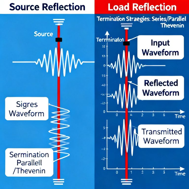
High-speed PCB design differs fundamentally from conventional low-speed circuit layout. When signal wavelength is comparable to trace length, PCB traces act as transmission lines rather than simple wires. Without precise impedance control, unwanted signal reflection, ringing, EMI radiation and crosstalk will occur, leading to intermittent connection failure, communication dropout and low production yield. This is why high speed pcb impedance values are critical for reliable system operation.
Standard impedance values including 50Ω, 75Ω, 90Ω and 100Ω are not random numbers. They are unified and defined by IPC industry standards, interface associations such as USB-IF, PCI-SIG, IEEE Ethernet, and leading EDA companies like Cadence. Adopting these high speed pcb impedance values ensures cross-brand interoperability between chips, connectors and system boards.
Adopting industry standard impedance brings three core benefits:
- Ensures cross-brand interoperability between chips, connectors and system boards
- Matches mainstream PCB manufacturing processes to control cost and improve yield
- Simplifies stackup design, shortens R&D cycle and avoids repeated layout rework
Whether you are designing consumer electronics, industrial control boards, server backplanes or communication equipment, mastering high speed pcb impedance values is the first step of reliable signal integrity design. For a complete overview of all high-speed PCB parameters, the PCB Parameters page covers Dk/Df, insertion loss, and material selection to complement your knowledge of impedance values.
Basic Concept: Single-Ended vs Differential Impedance
To correctly select impedance values, designers must first distinguish between single-ended and differential impedance, as both appear in standard high speed pcb impedance values tables.
Single-Ended Impedance refers to the characteristic impedance of a single trace referenced to a ground or power plane. It is widely used for clock signals, general high-speed I/O, RF circuits and DDR data lines. Simple in structure, easy to route, and compatible with most conventional PCB stackups.
Differential Impedance consists of two tightly coupled parallel traces transmitting complementary opposite-phase signals. Differential signaling naturally suppresses common-mode noise, resists external electromagnetic interference and reduces crosstalk. It has become the mainstream solution for high-speed serial interfaces above gigabit rate.
All mainstream high-speed protocols clearly define separate single-ended and differential high speed pcb impedance values; mixing them up is one of the most common design mistakes for junior engineers.
Standard Single-Ended Impedance Values & Applications
Single-ended impedance has fixed industry standard values with unified tolerance and mature application scenarios. The following table summarizes the most commonly used specifications following IPC and industrial design norms:
| 50Ω | ±10% | Universal high-speed digital signals, RF circuits, system clock lines |
| 75Ω | ±10% | SDI, CVBS, analog video transmission, coaxial matched video |
| 40–60Ω | Custom per chip | DDR4 / DDR5 DQ, DQS data and strobe lines |
| 28Ω | Custom | Low-power DDR special design |
Among all single-ended high speed pcb impedance values, 50Ω is the universal golden standard. It achieves the optimal balance between signal attenuation, power handling capability and PCB manufacturing feasibility. On common FR-4 dielectric material, 50Ω traces adopt regular width, which fits mass production processes well. 75Ω is dedicated to video signal matching, consistent with traditional coaxial cable impedance to ensure long-distance analog video transmission without distortion.
Standard Differential Impedance Values & Industrial Use Cases
Differential pairs dominate modern high-speed serial transmission. Each standard value corresponds to fixed interface types and tolerance rules within high speed pcb impedance values:
| Impedance Value | Standard Tolerance | Typical Applications |
|---|---|---|
| 90Ω | ±10% | USB 2.0, USB 3.x, USB4 full differential pairs |
| 100Ω | ±10% | PCIe 3.0/4.0/5.0, Ethernet, HDMI, SATA, LVDS, general SerDes |
| 85Ω | ±10% | Special DDR5 controller differential clock pairs |
| 120Ω | ±10% | CAN bus, RS-485 industrial long-distance communication |
90Ω differential is exclusive to the entire USB protocol family regulated by USB-IF. Strict ±10% tolerance must be maintained to keep impedance continuity across PCB traces, connectors and cables. These high speed pcb impedance values are non-negotiable for USB compliance. 100Ω differential is the most widely adopted industry standard, supported by PCI-SIG, IEEE and HDMI Forum, perfectly matching mainstream SoC and FPGA transceivers.
PCB Impedance Values by Main High-Speed Protocols
For quick design reference, below is the unified impedance matching table for mainstream protocols, summarized from Cadence official design guidelines and Saturn PCB industry practice:
| Protocol / Interface | Single-Ended Impedance | Differential Impedance |
|---|---|---|
| PCIe 3.0/4.0/5.0 | 50Ω | 100Ω |
| USB 2.0 / USB 3.x / USB4 | 45Ω | 90Ω |
| 10/100/1000BASE Ethernet | 50Ω | 100Ω |
| 10GBASE-KR / 25GBASE-KR | 50Ω | 100Ω |
| HDMI 1.4 / 2.0 / 2.1 | 50Ω | 100Ω |
| SATA 2.0 / 3.0 | 50Ω | 100Ω |
| DDR4 / DDR5 | 40–60Ω | Not required |
| CAN / RS-485 | Not required | 120Ω |
Engineers can directly follow this table for stackup setup and routing rule configuration. Design-side impedance calculations — covered in Impedance Matching Ultimate — complement the protocol matching guidance here. Do not arbitrarily modify high speed pcb impedance values based on experience; any deviation will lead to protocol compliance test failure.
IPC Impedance Tolerance Grades & Cost Impact
Impedance tolerance defines the allowable deviation between actual manufactured impedance and target value. Referencing IPC-2221 standard, it is divided into three clear grades with direct impact on cost and production process for high speed pcb impedance values:
| Tolerance Grade | Tolerance Range | Application Scenarios | Cost Increase |
|---|---|---|---|
| Standard Grade | ±10% | Consumer electronics, general industrial control, below 10Gbps | Baseline |
| Strict Grade | ±7% | High-end communication, 25Gbps+ backplane, server motherboard | +10%–20% |
| Precision Grade | ±5% | 112G PAM4 ultra-high speed, aerospace, laboratory test equipment | +25%–40% |
±10% is the default choice for most projects, compatible with standard FR-4 materials and normal etching and lamination processes. Manufacturing tolerance control — detailed in Impedance Control in PCB Manufacturing — explains how these grades are achieved in production. For ultra-high-speed products, strict or precision tolerance must be confirmed with PCB manufacturers in advance to verify process capability and budget.
Custom Non-Standard Impedance: Feasibility, Risks & Suggestions
Besides standard 50Ω, 75Ω, 90Ω and 100Ω, designers can customize non-standard impedance such as 37.5Ω, 65Ω or 80Ω for special chips and proprietary interfaces. However, standard high speed pcb impedance values should always be the first choice.
Technically, modern multilayer PCB can realize almost any custom impedance value through adjusting trace width, pair spacing and dielectric thickness. However, custom impedance brings obvious drawbacks: requires customized PCB stackup, cannot use mature universal layer structure; may need special dielectric materials, longer production cycle and lower yield; extra simulation, sample testing and manufacturer communication cost.
Industry best practice: always prioritize standard high speed pcb impedance values. Only customize when chip datasheet or official protocol explicitly requires it, and inform the PCB factory at the stackup design stage. Proper stackup design is the foundation for achieving target impedance — Stackup Design provides detailed layer arrangements for controlled impedance.
Professional High-Speed PCB Impedance Design Checklist
Follow this checklist to avoid impedance errors and layout rework when working with high speed pcb impedance values:
- Classify all signals and confirm single-ended / differential type first
- Assign 50Ω default for general single-ended, 75Ω for video, 40–60Ω for DDR
- Match differential pairs: 90Ω for USB, 100Ω for PCIe/Ethernet/HDMI, 120Ω for CAN
- Confirm impedance tolerance grade: use ±10% for regular projects
- If custom impedance is needed, communicate feasibility with PCB supplier early
- Mark all controlled impedance networks and tolerance clearly in fabrication drawings
Key Takeaways
- 50Ω single-ended and 100Ω differential are the universal benchmark for high speed pcb impedance values
- 90Ω is dedicated to full USB series; 75Ω for video signals; 120Ω for industrial CAN/RS-485
- Strictly follow protocol impedance tables instead of empirical setting
- ±10% tolerance balances cost and performance for most commercial and industrial products
- Custom non-standard impedance is feasible but increases cost, cycle and production risk; use only when necessary
- Correct impedance selection is the cheapest and most effective way to ensure signal integrity and mass production yield
FAQ About High-Speed PCB Impedance Values
Q1: Why is 50Ω the most common single-ended impedance in PCB design?
50Ω achieves the optimal balance between signal attenuation, power handling and PCB manufacturing feasibility. It is recognized as the universal standard by IPC, Cadence and most semiconductor vendors. This is a fundamental high speed pcb impedance values concept.
Q2: Can I use 100Ω differential instead of 90Ω for USB routing?
No. USB-IF strictly specifies 90Ω differential impedance. Random replacement will cause signal reflection, poor eye diagram and unstable transmission.
Q3: Is ±10% impedance tolerance enough for most projects?
Yes. ±10% standard tolerance fully meets consumer electronics, industrial control and mainstream 10Gbps and below high-speed interfaces. Only high-end ultra-high-speed equipment needs ±7% or ±5% for tighter high speed pcb impedance values control.
Q4: Can PCB manufacturers customize any non-standard impedance value?
Technically yes, but it will increase stackup complexity, material cost and production cycle. It is recommended to avoid custom impedance as much as possible.
Q5: Do DDR4 and DDR5 require differential impedance control?
Normally no. DDR memory only requires single-ended impedance control within 40–60Ω according to chip specifications.
Get Professional Impedance Design & PCB Quotation Support
Choosing the right high speed pcb impedance values, designing reasonable PCB stackup and confirming manufacturing tolerance are critical steps to ensure product stability and mass production yield. If you need help with impedance value selection, high-speed stackup design, impedance calculation, or formal PCB manufacturing quotation, our professional engineering team can provide one-stop technical support.
We offer: Free impedance scheme review • High-speed stackup design • Impedance calculation • Process feasibility confirmation • Competitive PCB manufacturing quotation
You can send your PCB design files, interface requirements and speed specifications to us. We will offer free impedance scheme review, process feasibility confirmation and competitive factory quotation, helping you avoid design risks and save R&D and production cost.
About HighSpeedPCBs.com
We are a specialized PCB design and manufacturing service provider serving industrial, automotive, medical, and communications OEMs worldwide. Complete high-speed PCB parameter documentation, including impedance, loss, and material specifications, is available in the PCB Parameters page. Our expertise in high speed pcb impedance values ensures your high-speed designs achieve reliable signal integrity.
© 2026 HighSpeedPCBs.com — Professional High-Speed PCB Solutions