Understanding reflection in transmission line for AC vs DC signals is critical for high-speed PCB design. This guide explains why DC signals settle without reflections, while AC signals require impedance control to maintain signal integrity.
In high-speed PCB design, reflection in transmission line for AC vs DC signals reveals fundamental differences. DC signals reach steady state without reflections, but AC signals continuously reflect at impedance discontinuities. Mastering this distinction is essential for reliable high-speed PCB performance.
Fundamentals of Reflection in Transmission Line for AC vs DC Signals
What is a Transmission Line?
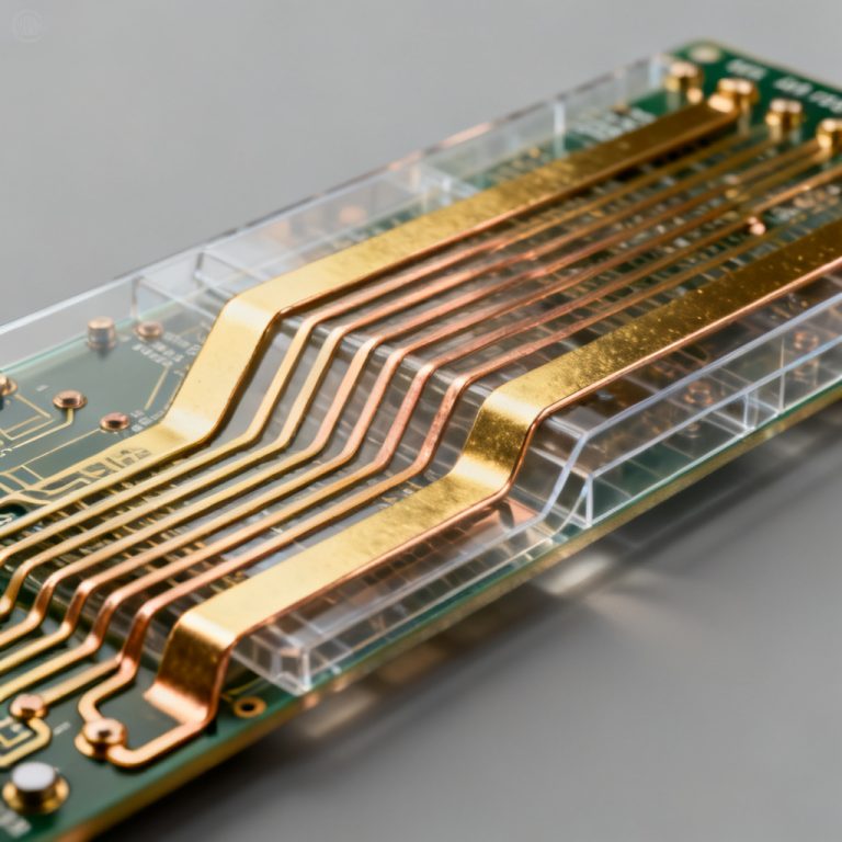
A transmission line is a specialized structure designed to carry electrical energy with minimal loss. In PCB design, common types include microstrip and stripline. When trace length exceeds 1/10th of signal rise-time wavelength, it must be treated as a transmission line.
Characteristic Impedance (Z0)
Every transmission line has a characteristic impedance (Z0) determined by geometry. For high-speed PCBs, Z0 is typically 50Ω single-ended or 100Ω differential. This ratio of voltage to current for a traveling wave defines reflection behavior.
Reflection Mechanism
Reflection occurs at impedance discontinuities like vias, connectors, or unmatched loads. The reflection coefficient (Γ) is:
Γ = (ZL – Z0) / (ZL + Z0)
- If ZL = Z0, Γ = 0 (no reflection)
- If ZL = ∞ (open), Γ = +1 (full reflection)
- If ZL = 0 (short), Γ = -1 (inverted reflection)
DC Signal Behavior: Why No Steady-State Reflection
Steady-State Analysis
DC signals represent constant voltage and current. After one round-trip delay, the line reaches steady state, behaving as a simple conductor with low DC resistance.
Reflection Behavior for DC Signals
In steady state, DC signals do not experience reflections. Voltage and current are constant everywhere. Impedance matching is irrelevant for steady-state DC. For example, a 5V source into a 50Ω line with 10kΩ load yields approximately 5V at the load regardless of mismatch.
Transient Reflections
During turn-on, a voltage step travels down the line. If load is mismatched, an initial reflection occurs. After one round-trip, equilibrium is reached. This transient reflection is identical to low-frequency AC behavior.
Practical Implications for DC Circuits
For pure DC power delivery, reflections are rarely a concern. The primary consideration is IR drop and PDN inductance, not impedance matching.
AC Signal Behavior: Continuous Reflection Challenge
Nature of AC Signals
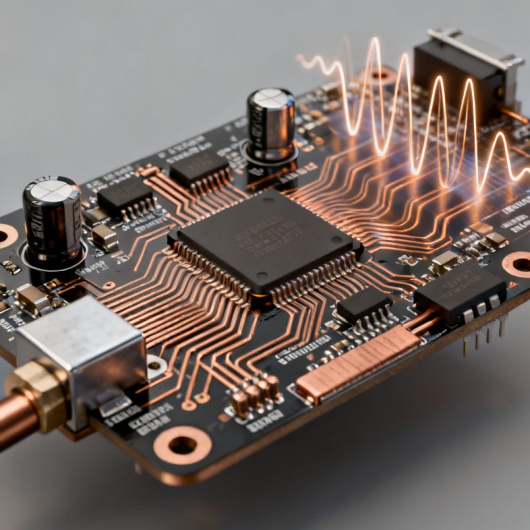
AC signals, including digital square waves with many harmonics, are time-varying. They continuously propagate as waves governed by characteristic impedance and termination.
Reflection Behavior for AC Signals
AC signals are continuously susceptible to reflections if impedance mismatches exist. At any Z0 change, a reflected wave is generated, interfering with the forward wave. This creates standing waves, ringing, overshoot, and signal distortion.
Standing Waves and VSWR
VSWR = (1 + |Γ|) / (1 – |Γ|). A VSWR of 1:1 indicates perfect match. VSWR of 2:1 or higher causes significant signal integrity issues.
Practical Implications for AC Circuits
Reflections cause ringing, overshoot, data errors, increased EMI, and reduced noise margins. Solution: proper termination (series, parallel, Thevenin, or AC) to match load impedance to Z0.
Core Differences: Reflection in Transmission Line for AC vs DC Signals
| Aspect | DC Signals (Steady-State) | AC Signals (Dynamic) |
|---|---|---|
| Reflection Occurrence | No reflections in steady state; transient only during turn-on/turn-off | Continuous reflections throughout propagation if mismatched |
| Impedance Matching Requirement | Not required for steady-state | Essential for signal integrity |
| Wave Behavior | No wave propagation in steady state | Continuous wave propagation with potential standing waves |
| Impact of Mismatch | No effect on final voltage | Causes ringing, overshoot, undershoot, data errors |
| Termination Strategy | Not needed for steady-state | Required (series, parallel, etc.) |
The fundamental truth: DC is a steady-state phenomenon; AC is a wave phenomenon. Transmission lines are waveguides, and for waves, impedance mismatches always cause reflections.
Reflection in transmission line for AC vs DC signals is a cornerstone of high-speed PCB design. DC signals settle without reflections, while AC signals demand continuous impedance control.
Real-World Examples in High-Speed PCB Design
Digital Clock Lines (AC-like)
A 100 MHz clock signal is a high-frequency AC signal. With 50Ω trace and 10kΩ receiver input, Γ ≈ 0.995, causing severe ringing. A series termination resistor (e.g., 33Ω) near the driver matches the line, eliminating reflections.
Power Supply Rails (DC-like)
A 3.3V power rail does not require impedance matching. Trace impedance (e.g., 30Ω or 70Ω) does not cause steady-state reflections. Transient reflections settle in nanoseconds. Primary concern is DC resistance and power plane inductance.
Mixed-Signal Systems
Digital traces must be impedance-controlled and terminated; power rails can be simple wide traces. Ensure continuous ground plane for digital signal return paths to avoid impedance discontinuities.
Mitigation Strategies for High-Speed PCB Design
Impedance Control
Manufacture PCBs with controlled impedance (e.g., 50Ω ±10%). Specify trace geometry and dielectric materials to your manufacturer.
Termination Techniques
- Series Termination: Resistor near driver such that Rs + Rout = Z0
- Parallel Termination: Resistor at load equal to Z0
- AC Termination: Resistor and capacitor in series at load
- Thevenin Termination: Two resistors (e.g., 100Ω to Vcc and 100Ω to GND)
Layout Best Practices
- Keep traces as short as possible
- Avoid stubs (unterminated branches)
- Use continuous ground planes
- Minimize via count on high-speed traces
- Route critical signals on inner layers (stripline)
Simulation and Verification
Use signal integrity simulation tools (e.g., HyperLynx, ADS) to model reflections. Measure TDR on prototypes to verify impedance.
FAQ: Reflection in Transmission Line for AC vs DC Signals
Why does reflection in transmission line for AC vs DC signals differ fundamentally?
DC signals reach steady state without wave propagation, so reflections cease after settling. AC signals are continuous waves; any impedance mismatch causes ongoing reflections.
Do I need impedance matching for DC power lines?
No. For steady-state DC, impedance matching is not required. Only transient reflections occur during power-up, which settle quickly.
What is the primary cause of reflection in transmission line for AC signals?
Impedance discontinuities such as vias, connectors, stubs, or unmatched loads cause reflections. The reflection coefficient Γ determines the magnitude.
How does reflection in transmission line for AC vs DC signals affect high-speed PCB design?
AC reflections cause ringing, overshoot, data errors, and EMI. DC reflections are negligible in steady state. Designers must terminate AC signals but can ignore DC impedance matching.
What termination is best for AC reflection in transmission line?
Series termination is common for digital signals. Parallel termination at the load also works. Selection depends on driver output impedance, load type, and power consumption.
Conclusion: Mastering Reflection for Reliable High-Speed Designs
The distinction between DC and AC reflection behavior is fundamental to high-speed PCB design. While DC signals are forgiving of impedance mismatches in steady state, AC signals demand strict impedance control and termination to prevent signal degradation. By understanding the wave nature of AC signals and applying appropriate termination strategies, you can ensure robust signal integrity in your high-speed PCB designs.
As a leading manufacturer of high-speed PCBs, we specialize in controlled impedance fabrication, advanced materials, and design-for-manufacturing support. Contact our engineering team for assistance with your next high-speed project.
Professional Terminology Explained
- Characteristic Impedance (Z0): The inherent impedance of a transmission line, determined by trace geometry and dielectric properties.
- Reflection Coefficient (Γ): Ratio of reflected voltage to incident voltage at an impedance discontinuity.
- VSWR: Voltage Standing Wave Ratio, a measure of impedance mismatch in AC systems.
- Standing Wave: Interference pattern created by forward and reflected waves on a transmission line.
- Time Domain Reflectometry (TDR): A measurement technique to locate impedance discontinuities in transmission lines.