Skip to content

High Speed PCBS

  • Contact
  • Home
  • Sample Page
High Speed PCBS

  • differential pair impedance calculation using Polar Si9000
    Differential Pair Routing | PCB Design Guidelines

    How to Calculate Differential Pair Impedance Using Polar Si9000 Step by Step

    Master differential pair impedance calculation using Polar Si9000 with this comprehensive guide. This step-by-step tutorial covers stackup setup, field solver configuration, edge-coupled vs. broadside models, and common errors—essential for high-speed PCB designers and B2B buyers seeking controlled impedance manufacturing. 1. Understanding Differential Pair Impedance Basics Differential pair impedance calculation using Polar Si9000 begins with fundamental…


    Read More How to Calculate Differential Pair Impedance Using Polar Si9000 Step by StepContinue

  • Differential Pair Impedance Coupon
    Differential Pair Routing | PCB Design Guidelines

    Differential Pair Impedance Coupon Layout How to Design Test Strips

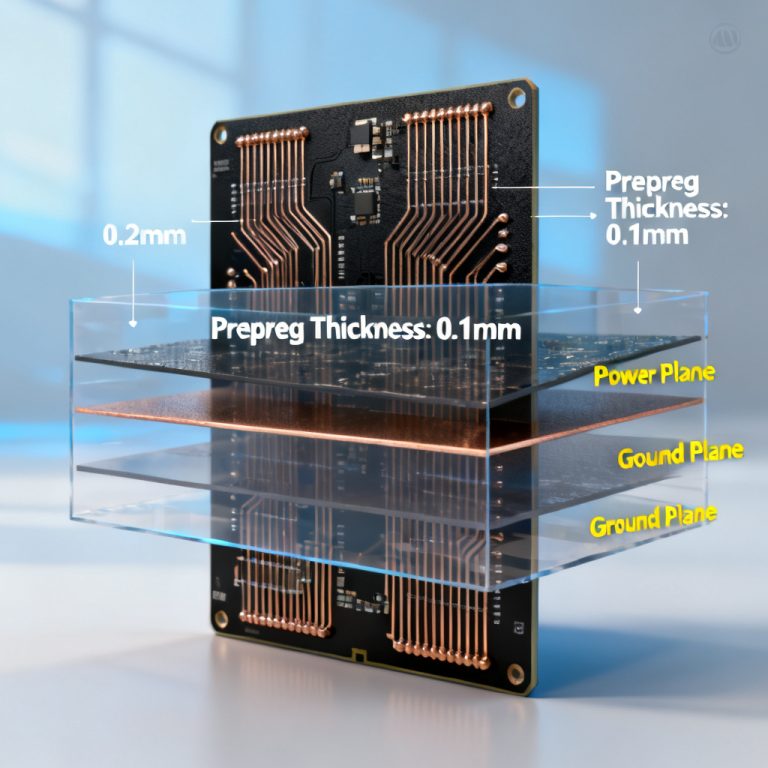
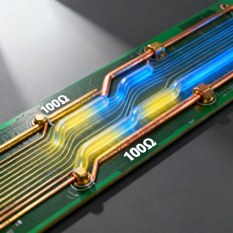
    In high-speed digital and RF applications, a Differential Pair Impedance Coupon is essential for verifying that controlled impedance targets (e.g., 100Ω differential, 90Ω USB, 85Ω PCIe) are met during PCB fabrication. A single mismatch can cause signal reflection, crosstalk, and timing errors. This comprehensive guide synthesizes authoritative insights from top industry sources to provide a…

    Read More Differential Pair Impedance Coupon Layout How to Design Test StripsContinue

  • differential pair impedance
    Differential Pair Routing | PCB Design Guidelines

    Edge Coupled vs Broadside Coupled Differential Pair Impedance Which Is Better

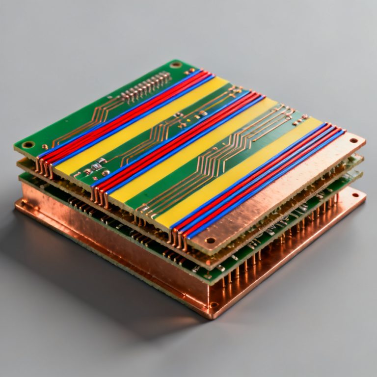
    In high-speed PCB design, differential pair impedance is the backbone of reliable data transmission. Protocols like USB, HDMI, PCIe, and Gigabit Ethernet rely on controlled differential impedance—typically 100Ω or 90Ω—to maintain signal integrity. This article compares edge-coupled vs broadside-coupled topologies to help you choose the best approach for your next high-speed board. The Fundamentals of…

    Read More Edge Coupled vs Broadside Coupled Differential Pair Impedance Which Is BetterContinue

  • dielectric height (H) changes differential pair impedance
    Differential Pair Routing | PCB Design Guidelines

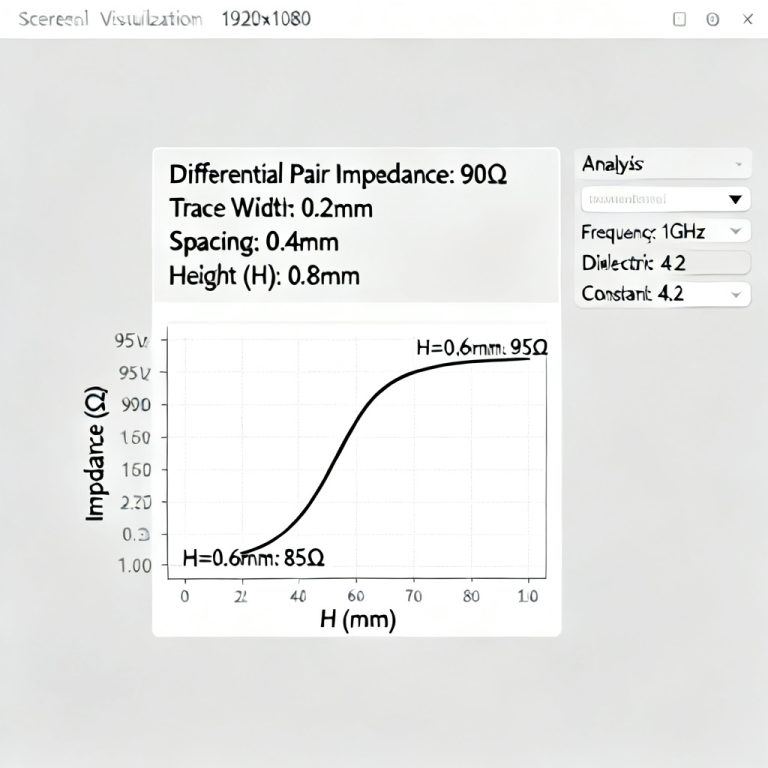
    How Dielectric Height H Changes Differential Pair Impedance The Most Sensitive Variable

    In high-speed PCB design, dielectric height (H) changes differential pair impedance more than any other variable. Understanding this sensitivity is critical for achieving 100 Ohm or 90 Ohm impedance targets in your custom high-speed PCB. Among all variables—trace width (W), trace spacing (S), copper thickness (T), and dielectric constant (Dk)—dielectric height (H) stands out as…

    Read More How Dielectric Height H Changes Differential Pair Impedance The Most Sensitive VariableContinue

  • differential pair impedance
    Differential Pair Routing | PCB Design Guidelines

    Differential Pair Impedance for Microstrip vs Stripline Different Formulas Apply

    In high-speed PCB design, differential pair impedance for microstrip vs stripline requires different formulas, as the electromagnetic fields and reference planes differ fundamentally. This page provides complete, authoritative guidance for achieving 100Ω or 90Ω target impedance in both topologies, helping you avoid costly signal integrity errors. Whether you are routing USB, HDMI, PCIe, or Gigabit…

    Read More Differential Pair Impedance for Microstrip vs Stripline Different Formulas ApplyContinue

  • Solder mask significantly affects differential pair impedance
    Differential Pair Routing | PCB Design Guidelines

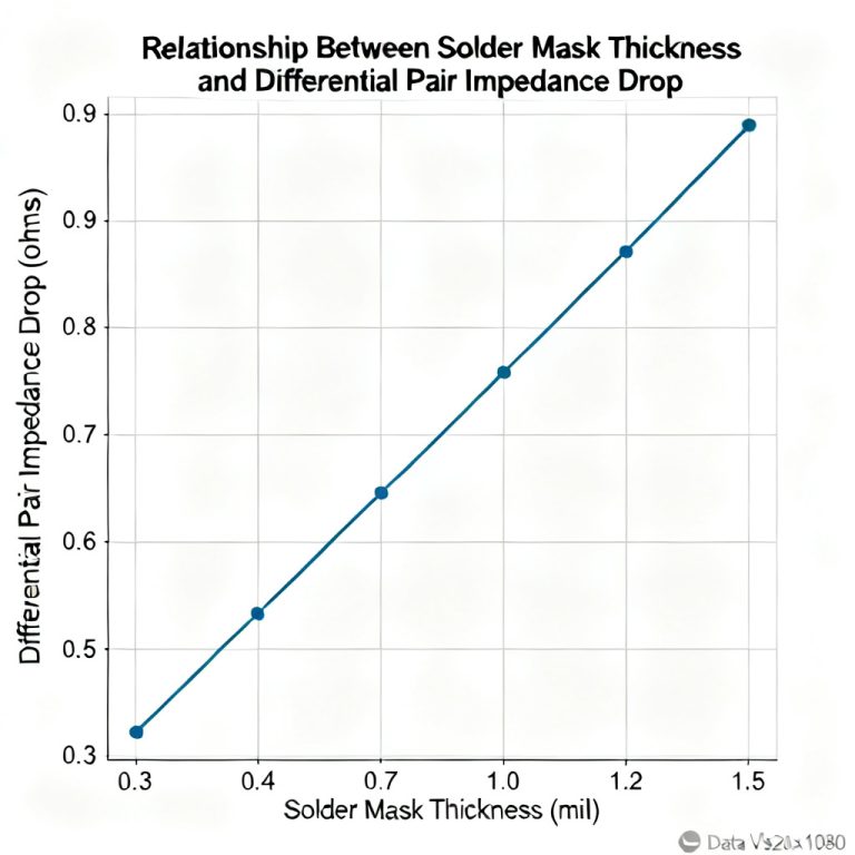
    How Solder Mask Affects Differential Pair Impedance How Much to Compensate

    Solder mask significantly affects differential pair impedance in high-speed PCB design, often causing a drop of 2–8 ohms that must be compensated. This guide explains why solder mask alters impedance, quantifies the change, and details proven compensation methods for 100-ohm, 90-ohm, and 85-ohm differential pairs used in USB 3.0, PCIe Gen4/5, and HDMI 2.1 interfaces….

    Read More How Solder Mask Affects Differential Pair Impedance How Much to CompensateContinue

  • differential pair impedance
    Differential Pair Routing | PCB Design Guidelines

    Differential Pair Impedance for Tight vs Loose Coupling Trade Offs Explained

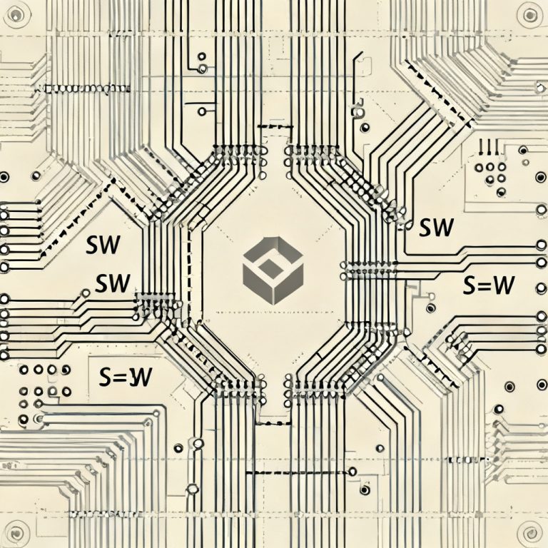
    In high-speed PCB design, understanding differential pair impedance trade-offs between tight and loose coupling is critical for signal integrity. This guide explains the key differences, impedance control strategies, and practical design choices for B2B engineers and procurement specialists. Introduction: The Foundation of High-Speed PCB Design In high-speed PCB design, differential pairs are the backbone of…

    Read More Differential Pair Impedance for Tight vs Loose Coupling Trade Offs ExplainedContinue

  • differential pair impedance
    Differential Pair Routing | PCB Design Guidelines

    How to Calculate Differential Pair Impedance from Single Ended Z0 and Coupling Coefficient

    Master the precise differential pair impedance calculation using single-ended Z0 and coupling coefficient (K). This guide covers core equations, practical PCB design formulas, and how coupling impacts impedance for high-speed signals. Core Variables for Differential Pair Impedance Calculation Before diving into equations, define three key parameters every differential pair impedance calculation relies on. Single-Ended Impedance…

    Read More How to Calculate Differential Pair Impedance from Single Ended Z0 and Coupling CoefficientContinue

  • skew between P and N affects differential pair impedance and common mode noise
    Differential Pair Routing | PCB Design Guidelines

    How Skew Between P and N Affects Differential Pair Impedance and Common Mode Noise

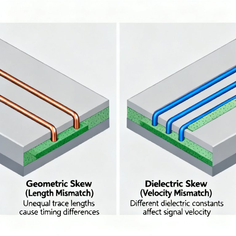
    In high-speed PCB design, understanding how skew between P and N affects differential pair impedance and common mode noise is critical for maintaining signal integrity. This page explains the physics, manufacturing realities, and mitigation strategies for this silent killer of high-speed performance. Section 1: The Foundation – What is Skew in a Differential Pair? Skew,…

    Read More How Skew Between P and N Affects Differential Pair Impedance and Common Mode NoiseContinue

  • Differential pair impedance at discontinuities
    Differential Pair Routing | PCB Design Guidelines

    Differential Pair Impedance at Discontinuities Vias Pads and Connectors

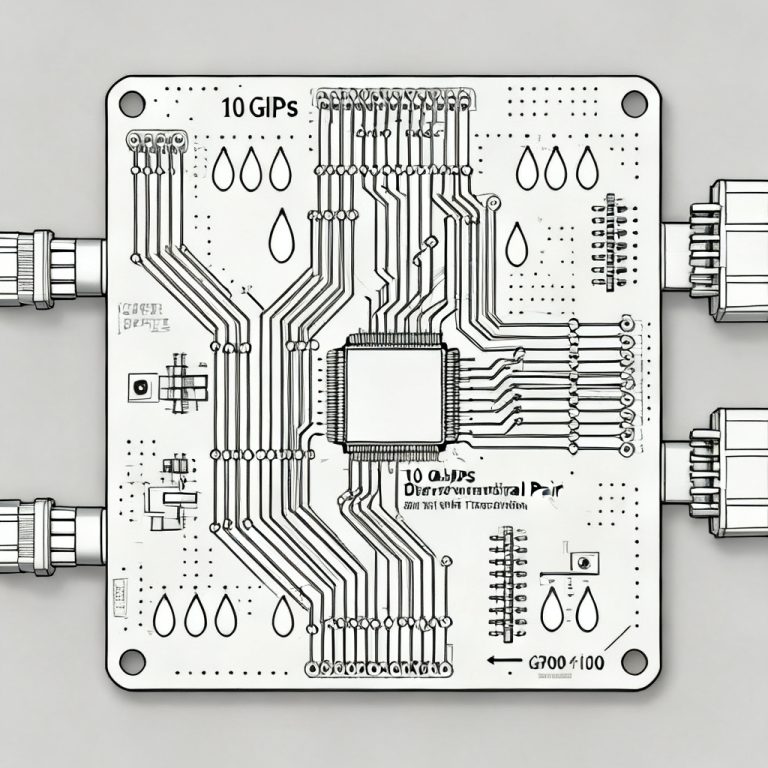
    Differential pair impedance at discontinuities—specifically at vias, pads, and connectors—is a critical factor in high-speed PCB design, directly impacting signal integrity and data transmission reliability. This comprehensive guide explores the physics, modeling, and mitigation strategies for maintaining controlled impedance across these common discontinuity points, ensuring robust performance for designs operating at 10 Gbps and beyond….

    Read More Differential Pair Impedance at Discontinuities Vias Pads and ConnectorsContinue

Page navigation

1 2 3 … 35 Next PageNext

© 2026 High Speed PCBS Powered by highspeedpcbs.com

  • Contact
  • Home
  • Sample Page