Eye diagram jitter high speed PCB analysis is the most fundamental method to evaluate signal quality and verify protocol compliance. This comprehensive guide covers eye mask compliance, complete jitter classification (RJ/DJ/DDJ/DCD/PJ), root causes, measurement setup, and PCB optimization for PCIe/USB/Ethernet/DDR. Eye diagram jitter high speed PCB testing is mandatory for product certification.
This eye diagram guide is part of our Signal Integrity Guide.
Table of Contents
- 1. What Is an Eye Diagram?
- 2. How to Read an Eye Diagram: Key Parameters
- 3. Ideal Eye vs Problematic Eye
- 4. Eye Mask & Compliance Standards
- 5. Understanding Jitter in High-Speed Signals
- 6. Root Causes of Eye Closure
- 7. How to Improve Eye Diagram in PCB Design
- 8. Measurement Guide
- 9. Interface Requirements Table
- 10. Key Takeaways
- 11. FAQ
- 12. Get Professional Support
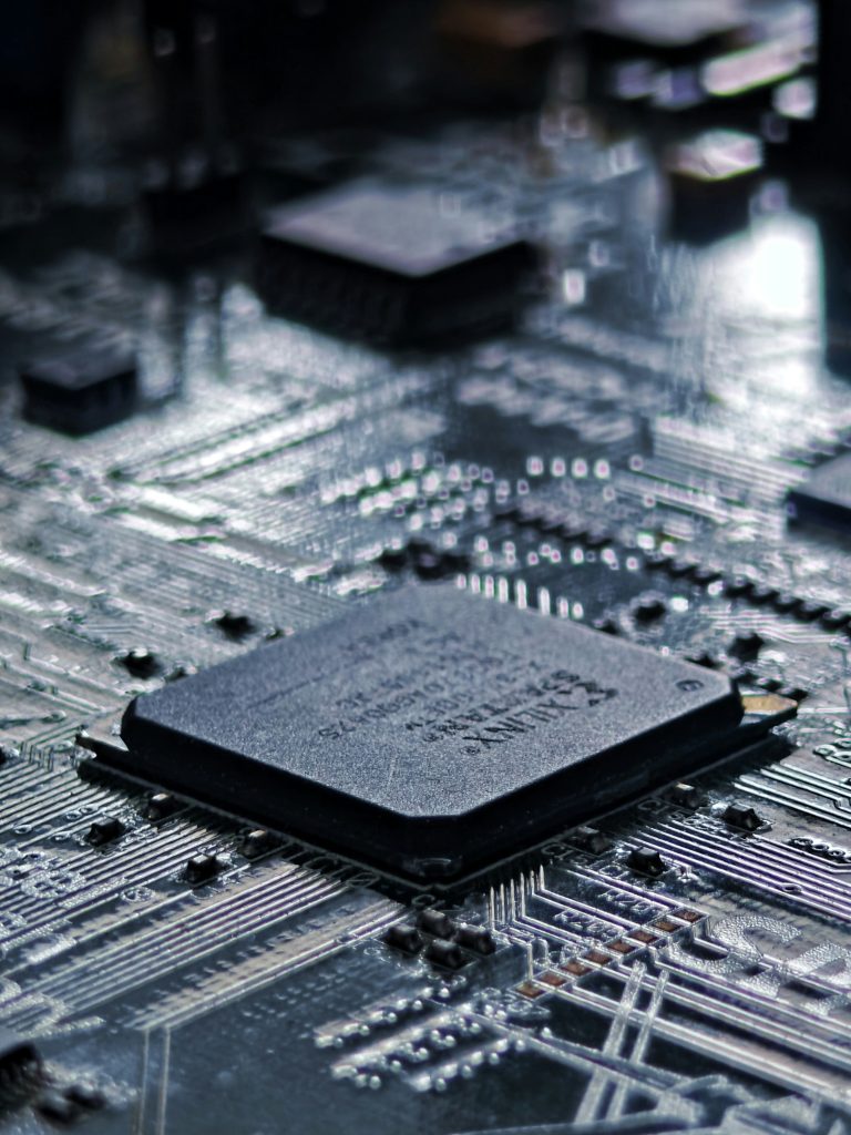
What Is an Eye Diagram in High Speed PCB?
An eye diagram is a composite waveform generated by overlapping thousands to millions of random signal cycles on an oscilloscope. The stacked shape resembles a human eye. Understanding eye diagram jitter high speed PCB is essential for any hardware engineer working with gigabit interfaces.
Unlike a single pulse waveform, an eye diagram visually combines voltage amplitude, noise margin, timing jitter, edge distortion, and intersymbol interference (ISI) into one graph. Engineers can judge overall high speed PCB eye diagram quality at a glance without complex calculation.
Core Functions of Eye Diagram:
- Evaluate high-speed signal integrity performance
- Check eye mask compliance against PCIe/USB/Ethernet standards
- Locate faults: noise, reflection, crosstalk, attenuation
- Guide PCB layout revision and material selection
When performing eye diagram jitter high speed PCB analysis, both parameters must be evaluated together for complete signal quality assessment.
How to Read an Eye Diagram: Key Parameters Explained
To interpret an eye diagram professionally, you must master the core parameters. Each parameter in eye diagram jitter high speed PCB analysis corresponds to a specific signal performance indicator.
| Parameter | Definition | Engineering Meaning |
|---|---|---|
| Eye Height | Vertical opening amplitude | Signal-to-noise ratio; larger = better noise immunity |
| Eye Width | Horizontal opening width | Timing margin; wider = more jitter tolerance |
| Eye Amplitude | Logic high-low voltage difference | Receiver judgment ability |
| Rise/Fall Time | Edge transition steepness | High-frequency integrity |
| Duty Cycle Distortion | Positive/negative pulse width difference | Clock quality, differential pair balance |
For impedance control affecting eye height, see our Impedance Matching Guide.
Ideal Eye Diagram vs Problematic Eye Diagram
When conducting eye diagram jitter high speed PCB analysis, engineers can quickly match abnormal eye phenomena with root PCB design causes.
| Signal Issue | Eye Diagram Performance | Root Causes |
|---|---|---|
| Random noise | Blurred upper/lower boundaries | Thermal noise, power ripple |
| Deterministic jitter | Horizontal narrowing | Reflection, crosstalk, ISI |
| Overshoot/undershoot | Sharp spikes | Impedance mismatch, via stub |
| Low amplitude | Vertical compression | Excessive insertion loss |
| Severe closure | Eye almost disappears | Loss + reflection + crosstalk |
For crosstalk-induced eye closure, see our Crosstalk Guide.
Eye Mask Definition & Industry Compliance Standards
An eye mask is a protocol-defined forbidden zone overlaid on the eye diagram. Eye mask compliance is mandatory for high-speed interface certification. If any waveform enters the mask → non-compliant → communication error.
| Protocol | Min Eye Height | Min Eye Width |
|---|---|---|
| PCIe 3.0 | 60 mV | 0.4 UI |
| PCIe 4.0 | 30 mV | 0.3 UI |
| PCIe 5.0 | 20 mV | 0.25 UI |
| USB 3.2 | 100 mV | 0.5 UI |
| 10GbE | 100 mV | 0.5 UI |
| 25GbE | 50 mV | 0.3 UI |
As transmission rate increases, eye mask compliance standards become stricter, requiring tighter impedance control and low-loss materials.
Understanding Jitter in High-Speed Signals
Jitter refers to the time deviation of signal edges from their ideal position. In eye diagram jitter high speed PCB analysis, jitter narrows eye width directly, reduces timing margin, and raises bit error rate.
Jitter Overall Classification:
| Type | Abbr | Characteristics | Nature |
|---|---|---|---|
| Total Jitter | TJ | Sum of all timing deviations | Overall index |
| Random Jitter | RJ | Unbounded, Gaussian | Device thermal noise |
| Deterministic Jitter | DJ | Bounded, repeatable | PCB layout, channel |
Deterministic Jitter (DJ) Subtypes:
| Subtype | Abbr | Typical Cause |
|---|---|---|
| Data Dependent Jitter | DDJ | Channel bandwidth shortage, ISI |
| Duty Cycle Distortion | DCD | Unmatched rise/fall time, unbalanced differential pair |
| Periodic Jitter | PJ | Power ripple, clock interference |
Understanding random jitter vs deterministic jitter is critical because RJ is unbounded while DJ can be predicted and minimized through better PCB design.
For differential pair balance affecting DCD, see our Differential Pair Routing Guide.
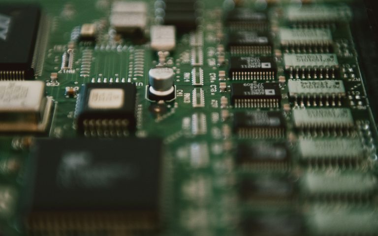
Root Causes of Eye Closure and Excessive Jitter
All eye diagram degradation and jitter issues trace back to PCB design, material and power integrity factors. Eye diagram jitter high speed PCB problems are typically caused by:
| Factor | Impact on Eye | Impact on Jitter |
|---|---|---|
| Excessive insertion loss | Lower eye height | Increase DDJ |
| Impedance mismatch | Overshoot, distortion | Aggravate DCD/DDJ |
| Severe crosstalk | Blurred boundary | Add crosstalk jitter |
| Power noise | Blurred edges | Increase RJ/PJ |
| Poor reference clock | Narrow eye width | Add PJ |
For reference plane issues affecting power noise, see our Return Path Guide.
How to Improve Eye Diagram & Reduce Jitter in PCB Design
Design Phase Methods (Fundamental Prevention):
- Precise impedance control (±10%)
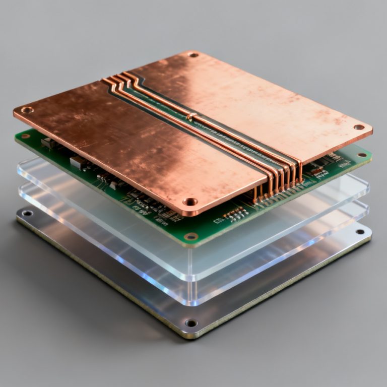
- Low-loss PCB material (low Dk/Df)
- Optimized decoupling capacitor layout
- Strict differential pair length matching
- Back-drill unused via stubs
- Reasonable trace spacing (3W/4W rule)
Debug Phase Methods (Post-Solution Remedy):
- Add or adjust termination resistors
- Enable receiver equalization (CTLE, DFE)
- Optimize power filtering and ground plane
Proper eye diagram jitter high speed PCB optimization in design phase is always more effective than post-production debugging.
Professional Eye Diagram & Jitter Measurement Guide
Required Test Equipment for Eye Diagram Jitter High Speed PCB Analysis:
| Equipment | Function |
|---|---|
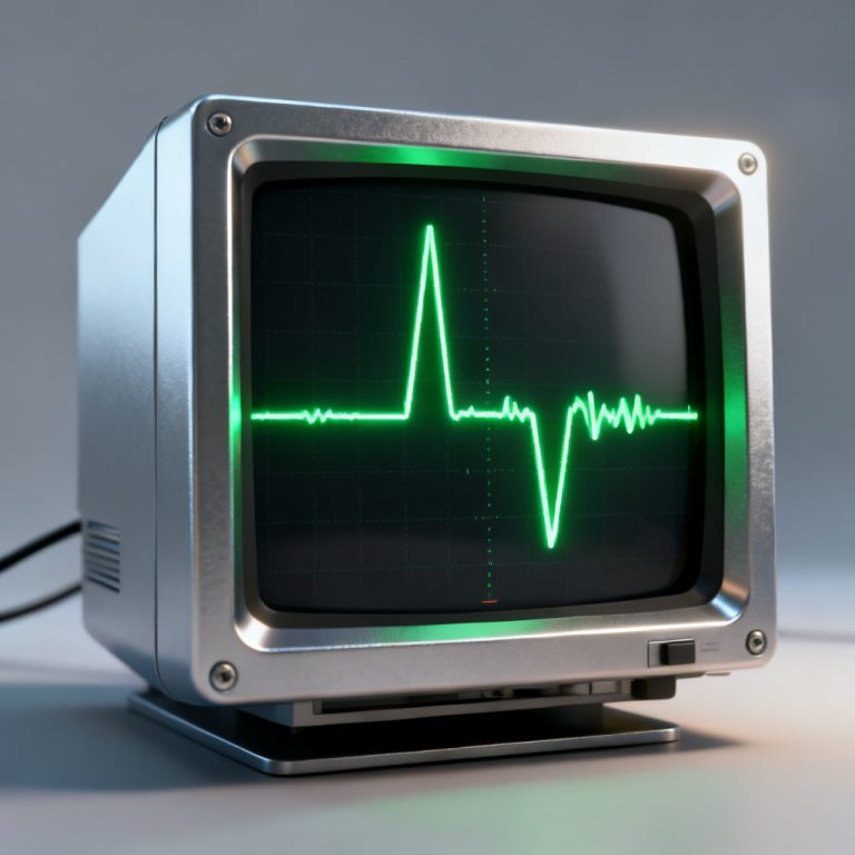
| High-speed sampling oscilloscope | Capture waveforms, generate eye diagram |
| Clock recovery module | Extract reference clock |
| Jitter analysis software | Decompose TJ/RJ/DJ components |
| High-frequency probe | Avoid extra noise |
Critical Measurement Rules:
- Capture at least 1 million bits of waveform data
- Sampling rate ≥ 4× signal data rate
- Bandwidth ≥ 5× signal fundamental frequency (5x rule)
Standard Jitter Decomposition Workflow: Measurement → Separate RJ and DJ → Identify PJ/DDJ/DCD → Locate root causes → Optimize design → Re-measure verification
Eye Diagram & Jitter Requirements by High-Speed Interface
| Interface | Data Rate | Min Eye Height | Min Eye Width | Max TJ |
|---|---|---|---|---|
| PCIe 3.0 | 8 GT/s | 60 mV | 0.4 UI | 0.3 UI |
| PCIe 4.0 | 16 GT/s | 30 mV | 0.3 UI | 0.25 UI |
| PCIe 5.0 | 32 GT/s | 20 mV | 0.25 UI | 0.2 UI |
| USB 3.2 Gen1 | 5 Gbps | 100 mV | 0.5 UI | 0.3 UI |
| USB 3.2 Gen2 | 10 Gbps | 80 mV | 0.4 UI | 0.25 UI |
| 100G-KR4 | 25.78 Gbps | 50 mV | 0.3 UI | 0.2 UI |
Higher speed means tighter eye mask compliance requirements, demanding higher precision in PCB fabrication and material selection.
Key Takeaways for Eye Diagram Jitter High Speed PCB Analysis
- The eye diagram is the most intuitive tool for evaluating high speed PCB eye diagram quality
- Eye height = SNR margin; Eye width = timing jitter margin
- Jitter splits into Random (RJ) and Deterministic (DJ: DDJ/DCD/PJ)
- Eye mask compliance is mandatory for PCIe/USB/Ethernet certification
- Root causes: insertion loss, impedance mismatch, crosstalk, power noise
- Fundamental fix = PCB design optimization; debugging = partial remedy
- Understanding random jitter vs deterministic jitter guides targeted mitigation
Return to the Signal Integrity Guide for more coverage of impedance, return path, differential pairs, and crosstalk.
Frequently Asked Questions About Eye Diagram Jitter High Speed PCB
Q1: What is the difference between eye height and eye width?
Eye height represents voltage noise margin; eye width represents timing jitter margin. Both are core pass/fail indicators for eye diagram jitter high speed PCB compliance.
Q2: What causes eye diagram closure most often?
Excessive insertion loss, impedance mismatch, crosstalk, power noise, and intersymbol interference are the top reasons for eye diagram closure.
Q3: What is the difference between RJ and DJ jitter?
Random jitter vs deterministic jitter: RJ is unbounded Gaussian noise from device thermal effects; DJ is bounded, repeatable jitter from PCB layout and channel characteristics.
Q4: Can eye problems be fixed only by PCB layout change?
Most inherent problems require layout/stackup/material optimization. Debugging can only partially help restore eye mask compliance.
Q5: What oscilloscope bandwidth for PCIe 4.0?
Follow the 5x rule: bandwidth ≥ 5× signal fundamental rate for accurate eye diagram jitter high speed PCB measurement.
Need Professional Eye Diagram & Jitter Analysis Support?
Struggling with eye diagram closure or jitter over-limit? Our engineering team provides one-stop technical services for global buyers and hardware engineers.
We offer: Eye diagram & jitter simulation • Signal integrity analysis • PCB stackup optimization • High-speed interface compliance design (PCIe/USB/Ethernet/DDR) • Free design review
All design files strictly confidential. Response within one business day.
About HighSpeedPCBs.com
We are a specialized PCB design and manufacturing service provider serving industrial, automotive, medical, and communications OEMs worldwide.
© 2026 HighSpeedPCBs.com — Professional High-Speed PCB Solutions