Impedance control PCB performance is critically influenced by environmental temperature and humidity. For high-speed digital designs, even small shifts in impedance can degrade signal integrity. This guide explains the science and solutions for B2B buyers.
The Science of Impedance Control PCB Design
An impedance control PCB ensures signals travel without reflection or loss. The characteristic impedance (Z₀) is determined by four physical factors: dielectric constant (Dk), trace width (W), dielectric height (H), and copper thickness (T). The classic microstrip formula is approximately Z₀ ≈ 87/√(εr + 1.41) × ln(5.98H / (0.8W + T)). Environmental factors primarily alter Dk and H, shifting the target impedance.
How Temperature Affects Impedance Control PCB
Dielectric Constant Shift with Temperature
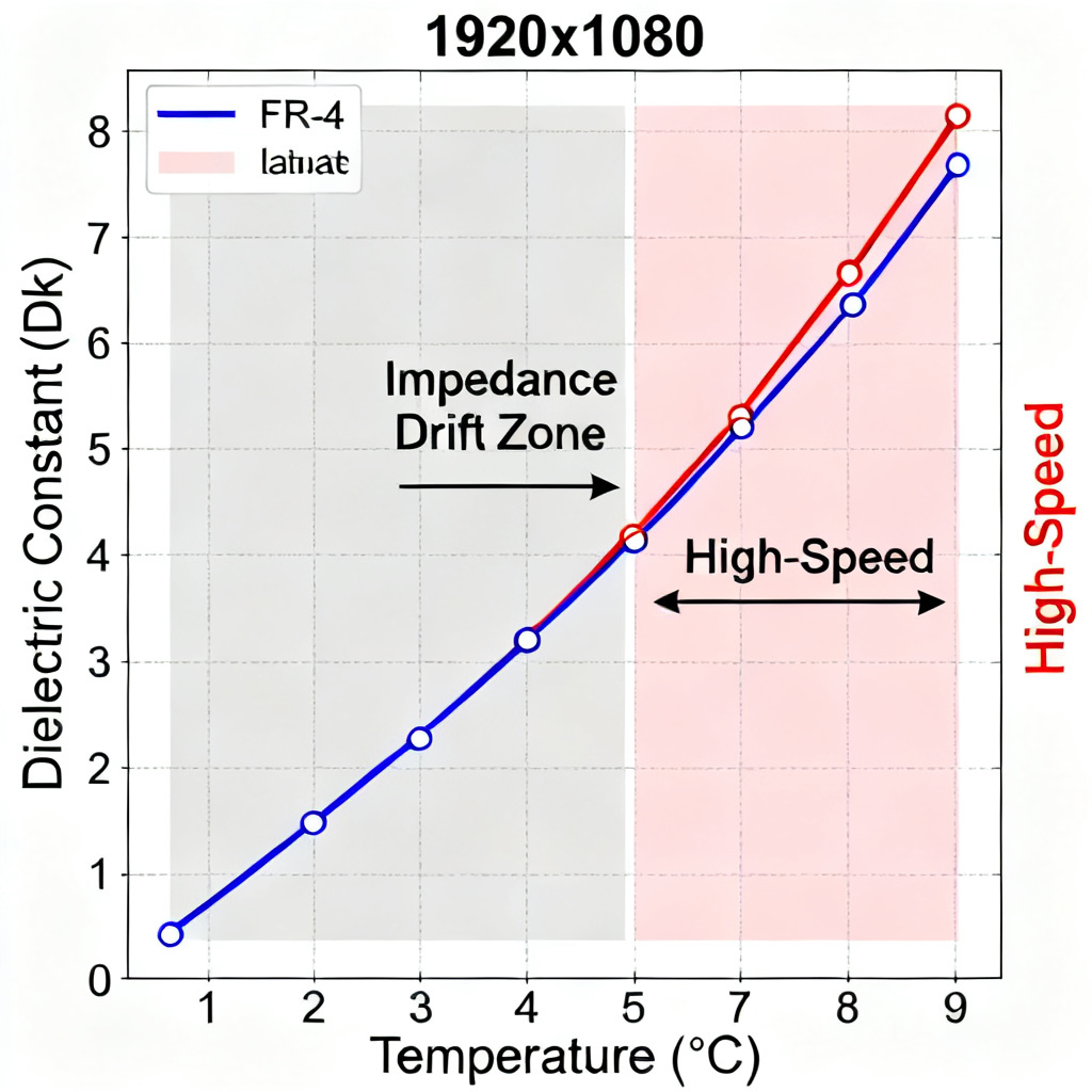
As temperature rises, the resin’s molecular structure becomes more mobile, increasing the dielectric constant (Dk). For standard FR-4, Dk can increase by 2% to 5% over -40°C to +125°C. For high-speed materials like Rogers or Megtron, this shift is typically below 0.5%. This Dk increase lowers the impedance control PCB value.
Thermal Expansion and Impedance
The Coefficient of Thermal Expansion (CTE) affects dielectric height (H). Z-axis expansion increases H, which raises impedance. This effect often opposes the Dk shift. The net result depends on the material. X/Y-axis CTE affects trace width but is less impactful.
Real-World Impact on High-Speed Signals
A 5% Dk shift can cause a 2.5% impedance change. For a 50-ohm line, this drifts to 48.75 or 51.25 ohms. In high-speed designs like DDR5 or PCIe Gen 5, this causes timing errors and jitter. Copper resistivity increases with temperature (0.4% per °C), increasing conductor losses. Above 1 GHz, dielectric loss dominates. Temperature also causes phase shifts in differential pairs.
Material Selection for Temperature Stability
Choose materials with low TCDk (e.g., Rogers 4350B, Isola IS420, Megtron 6), low Z-axis CTE, and high Tg (>170°C). High Tg FR-4, Polyimide, or PTFE composites are suitable for extreme environments.
How Humidity Affects Impedance Control PCB
Water Absorption and Dk Increase
Water has a dielectric constant of 78, dramatically higher than PCB laminates (Dk 3.0–4.5). When a impedance control PCB absorbs moisture, effective Dk increases by 1-3% even at 0.2% weight gain. Absorption is non-uniform, creating a Dk gradient across the board.
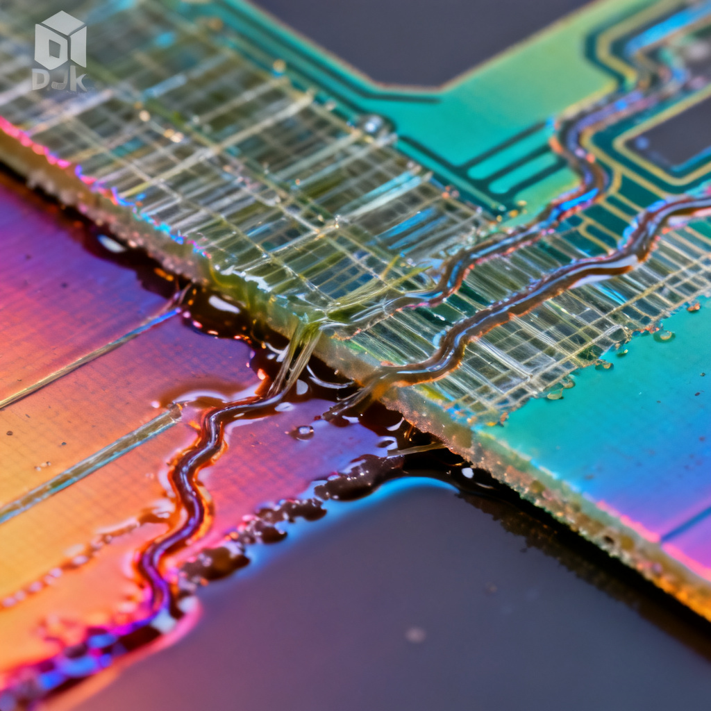
Swelling and Delamination Risks
Moisture causes hygroscopic swelling, increasing dielectric height. It also weakens the resin-glass bond, leading to measling, crazing, or delamination. Delamination introduces air gaps (Dk=1.0), causing extreme impedance spikes. High humidity and voltage bias can cause CAF growth, shorting layers.
Real-World Impact on High-Speed Signals
Impedance drops immediately. A 50-ohm line can fall to 48 ohms at 85% RH/85°C. Insertion loss increases due to higher Df. Drift is time-dependent (hours to days). Differential pair skew occurs if one trace absorbs moisture faster near board edges.
Material Selection for Humidity Resistance
Use materials with low moisture absorption: Rogers RO4000 series (0.04-0.06%), Polyimide (<0.3%), or PTFE-based (0.02%). Hydrophobic resin systems and low Z-axis CTE materials resist moisture ingress.
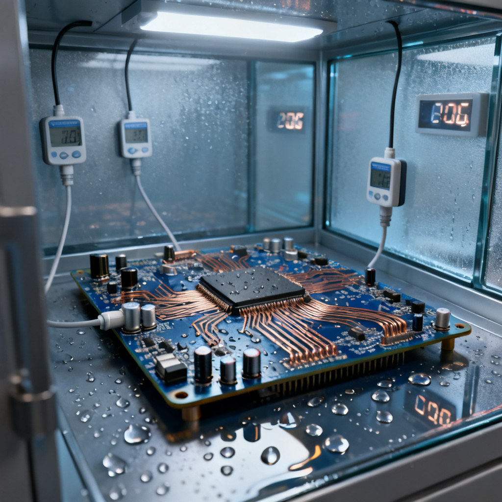
Combined Effects of Temperature and Humidity
In real-world applications, temperature and humidity act together. 85/85 testing (85°C, 85% RH) simulates this. High temperature accelerates moisture diffusion 10x. Total Dk shift can reach 5-8% in standard FR-4, causing a 2.5-4% impedance drop. Combined thermal and hygroscopic stress can cause rapid delamination. Corrosion at exposed copper accelerates.
Critical Application Examples
Automotive under-hood PCBs face -40°C to +150°C and 95% RH. Only high-Tg, low-moisture materials like Isola I-Tera MT40 or Rogers 3003 are suitable. Telecom base stations in tropical climates require stable impedance control PCB for 5G mmWave and 400G Ethernet. Data centers need low-TCDk materials for DDR5.
Design and Manufacturing Mitigations
Material Selection Summary Table
| Material Type | Dk Stability (TCDk) | Moisture Absorption | Best For |
|---|---|---|---|
| Standard FR-4 | Poor (200-400 ppm/°C) | 0.1-0.2% | Low-speed, controlled environment |
| High Tg FR-4 | Moderate (150-300 ppm/°C) | 0.1-0.15% | Moderate temp, low humidity |
| Rogers 4350B | Excellent (<50 ppm/°C) | 0.04% | High-speed, moderate temp/humidity |
| Isola IS420 | Excellent (<50 ppm/°C) | 0.08% | High-speed, high temp |
| Megtron 6 | Excellent (<40 ppm/°C) | 0.05% | Very high-speed, high temp/humidity |
| PTFE (e.g., RT/duroid) | Good (varies) | <0.02% | RF/microwave, extreme humidity |
Design Rules for Impedance Control PCB
Use differential pairs for critical lines. Minimize trace length. Avoid board edges for critical traces—keep at least 1 mm away. Provide solid ground planes. Add 3-5% impedance margin in simulation for environmental worst-case.
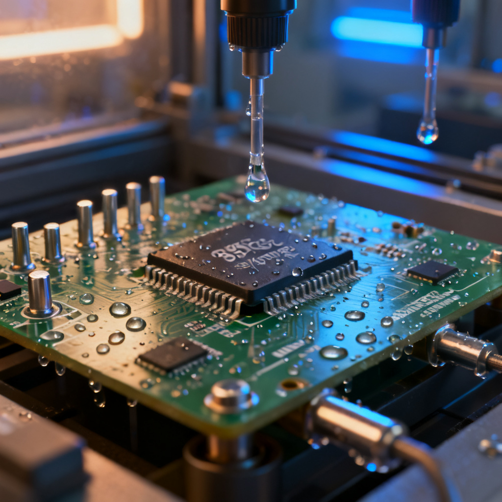
Manufacturing and Testing
Bake PCB at 105°C for 2-4 hours before impedance test. Test in controlled environment (23°C ± 2°C, 50% ± 5% RH) per IPC-2141A. Use calibrated TDR with rise time < 35 ps. Consider conformal coating for extreme humidity, but account for its Dk (2.5-3.5) in design.
Conclusion and Next Steps
Temperature and humidity are primary variables that affect impedance control PCB performance. Temperature shifts impedance through Dk increase and Z-axis expansion. Humidity lowers impedance through moisture absorption and can cause delamination. Material selection is the most effective mitigation. Design with 3-5% margins and test under controlled conditions.
At [Your Company Name], we specialize in manufacturing high-speed impedance control PCB that perform reliably in harsh environments. Our engineering team selects optimal material stackups, simulates environmental effects, and delivers boards with tight impedance tolerances (±5% or better). Contact us for a free stackup recommendation and 48-hour quick-turn quote.