To achieve accurate reflection in transmission line measurement, properly calibrating your TDR is the first and most critical step. This guide, tailored for high-speed PCB professionals, provides a definitive protocol for TDR calibration ensuring precise impedance validation for designs up to 25 Gbps and beyond.
Why TDR Calibration Matters for Accurate Reflection in Transmission Line Measurement
Before diving into calibration steps, understanding the physics behind TDR and why calibration is non-negotiable is essential for every accurate reflection in transmission line measurement.
The Principle of TDR Reflection Measurement
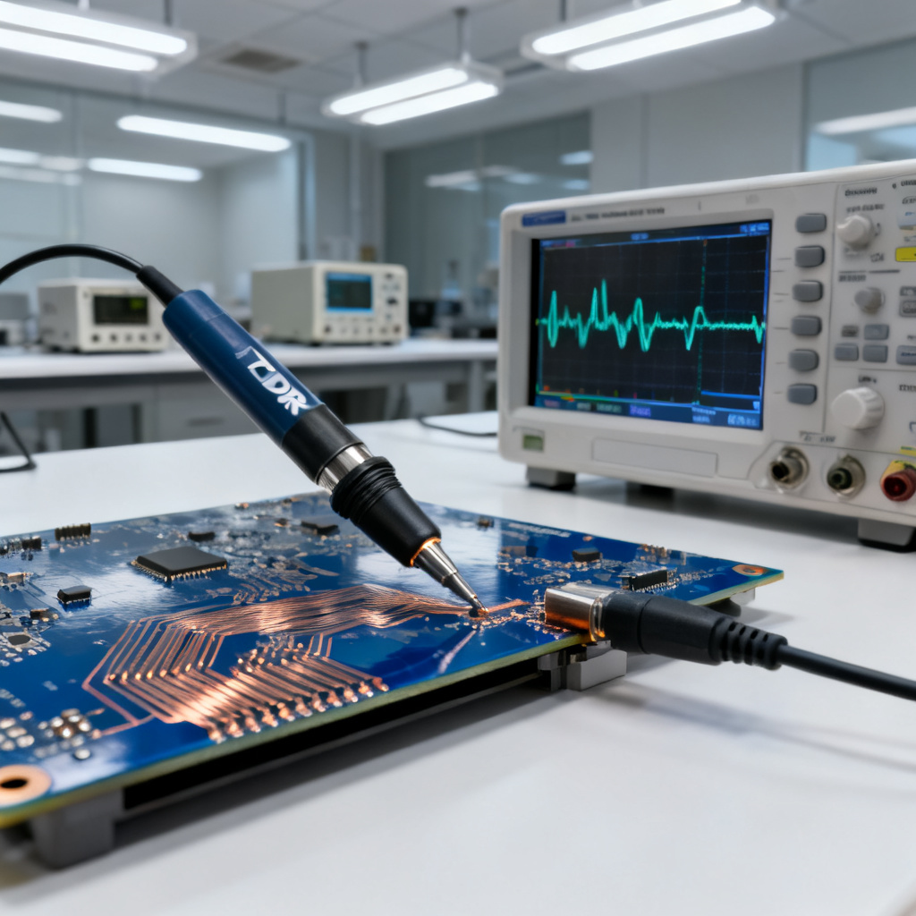
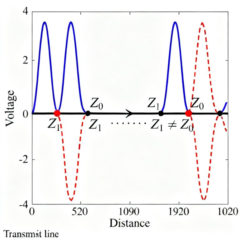
TDR works by launching a fast-rise-time step pulse (typically 35–50 ps for high-resolution measurements) into a transmission line. When the pulse encounters an impedance discontinuity—such as a change in trace width, a via, or a connector—a portion of the energy is reflected back to the source. By analyzing the reflected waveform in the time domain, the TDR instrument calculates the impedance at each point along the line. However, the raw reflected signal is affected by instrument internal delays and offsets, cable and probe losses, and connector and fixture parasitics. Without calibration, these artifacts are indistinguishable from actual transmission line discontinuities, leading to errors of 5–10% or more in impedance readings. For high-speed PCBs (e.g., 50-ohm differential pairs for 25 Gbps+ data rates), such errors can render a design non-functional.
The Goal of TDR Calibration
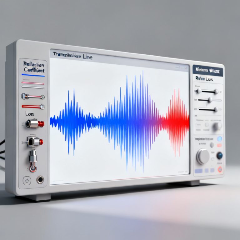
The primary objective is to establish a known reference plane—typically at the tip of the TDR probe or the end of the test cable—so that the measured reflection coefficient (Γ) corresponds only to the Device Under Test (DUT). This is achieved by removing systematic errors, setting a precise impedance reference, and defining the time-zero reference.
The Three-Step Calibration Protocol for Accurate Reflection in Transmission Line Measurement
Based on the combined expertise from Keysight, Tektronix, and Rohde & Schwarz, we present a three-step calibration procedure that covers all essential aspects. This protocol is applicable to both single-ended and differential TDR measurements.
Step 1: Establish a Clean Reference Plane (Open, Short, and Load Calibration)
This step removes the effects of the test cables, connectors, and internal instrument delays. It is analogous to a VNA calibration but adapted for TDR. Keysight emphasizes that the reference plane must be at the point where the DUT is connected. Use a precision calibration kit with known standards: an Open (high impedance), a Short (zero impedance), and a Load (e.g., 50 ohms). Tektronix adds that for high-accuracy TDR, you must account for the frequency-dependent behavior of these standards. For example, a 50-ohm load standard is not perfectly resistive at high frequencies; its parasitic capacitance must be modeled. Rohde & Schwarz highlights that the “Open” standard should be an ideal open circuit (infinite impedance), but in practice, it has a small fringing capacitance. The calibration algorithm corrects for this.
How to Perform It:
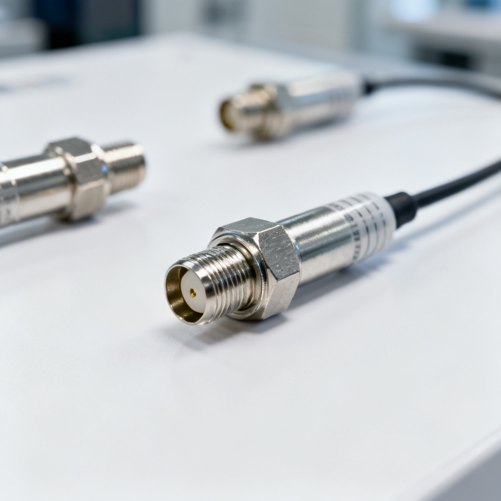
- Connect the calibration kit to the TDR test port (e.g., SMA female connector).
- Measure the Open standard: The TDR will display a large positive reflection (since Γ ≈ +1 for an open). Record the waveform.
- Measure the Short standard: Expect a large negative reflection (Γ ≈ -1). Record the waveform.
- Measure the Load standard: For a 50-ohm system, the load should produce a flat, near-zero reflection (Γ ≈ 0). Any deviation indicates cable loss or a non-ideal load.
- Apply the calibration algorithm: The instrument calculates the error coefficients (e.g., directivity, source match, reflection tracking) and stores them. After calibration, the TDR automatically subtracts these errors from all subsequent measurements.
Critical Note from Tektronix: Always perform the Open-Short-Load (OSL) calibration at the same temperature and with the same cable as your actual measurement. Thermal drift in cables (e.g., phase change) can invalidate the calibration.
Step 2: Set the Time Zero and Propagation Delay Compensation
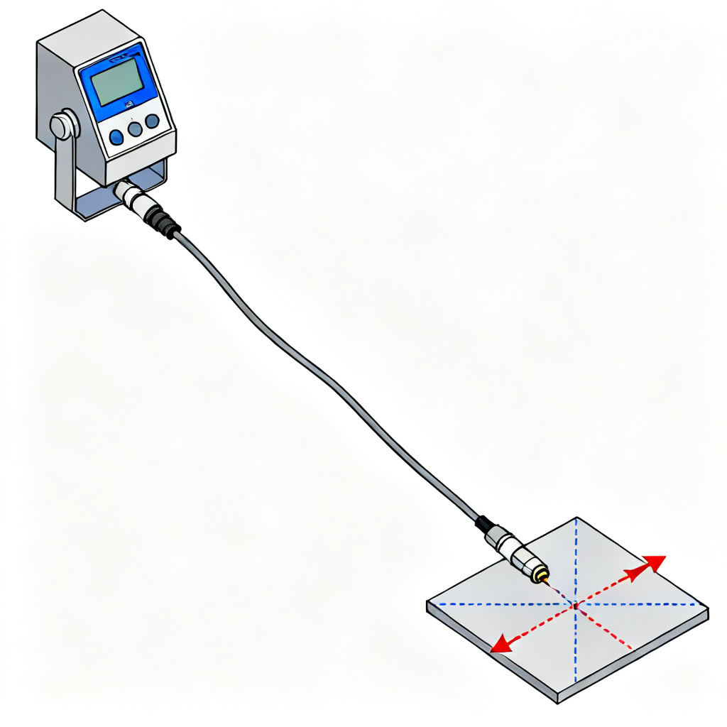
Time zero (T₀) is the exact moment the TDR pulse reaches the reference plane. Accurate time zero is vital for locating PCB impedance changes and analyzing Reflection and Termination issues, such as pinpointing a via 2.5 cm away from the connector.
Rohde & Schwarz emphasizes setting T₀ via standard impedance discontinuities like open-circuit transitions, with TDR calculating distance from round-trip delay. Keysight suggests reference plane markers on step pulse rising edges for precise calibration. Tektronix advises compensating probe/fixture delay by tuning propagation velocity or dielectric constant to align measured and actual lengths, ensuring accurate reflection and termination analysis.
How to Perform It:
- After OSL calibration, connect an Open standard at the reference plane.
- Observe the TDR waveform: The rising edge of the step pulse should be sharp (e.g., 35 ps rise time). The flat top after the step indicates the open reflection.
- Set the T₀ marker: On Keysight and Tektronix instruments, use the “Set Reference” or “Auto T₀” function. This places the cursor at the point where the step reaches 50% of its final amplitude.
- Validate with a known line: Connect a precision air-dielectric transmission line (e.g., 50-ohm airline) of known length (e.g., 10 cm). The TDR should show a flat impedance of 50 ohms along the line, with a clear reflection at the open end. The measured electrical length should match the physical length within 1–2% (accounting for the velocity factor).
Expert Insight from Rohde & Schwarz: For differential TDR (e.g., measuring differential impedance of a PCB pair), you must set separate time zeros for the two channels. Align them using a matched pair of open circuits to ensure the differential mode has zero skew.
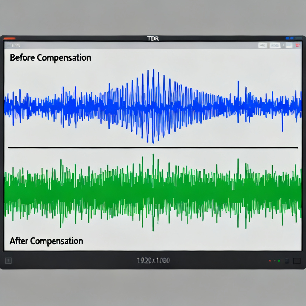
Step 3: Correct for Cable and Fixture Losses (Frequency-Dependent Attenuation)
Real-world cables and test fixtures attenuate and distort the TDR step pulse, especially at high frequencies. This causes the measured impedance to appear lower or to drift along the line (e.g., a 50-ohm line might read 48 ohms at 10 cm due to skin effect losses). Tektronix explains that cable loss compensation (also called “Loss Compensation” or “De-embedding”) is critical for long cables (>1 meter) or for measuring long transmission lines (>30 cm). Without it, the TDR will underestimate impedance at far-end points. Keysight offers a “Normalization” process: Measure a known low-loss standard (e.g., a precision 50-ohm load with a short cable) and use the instrument’s “Normalize” function to flatten the response. This subtracts the cable’s frequency-dependent attenuation. Rohde & Schwarz recommends using a “Time Domain Gating” technique: After calibration, apply a time gate (e.g., from 0 to 100 ps) to isolate the DUT response from cable reflections. However, this requires a clean reference plane from Step 1.
How to Perform It:
- Measure the cable response: Disconnect the DUT and leave the test cable open or terminated with a 50-ohm load. Record the TDR waveform over the full time window.
- Apply loss compensation: On modern TDRs (e.g., Keysight DCA-X or Tektronix DSA8300), select “Loss Compensation” from the calibration menu. The instrument uses the recorded cable response to calculate a correction filter (typically a 1/sqrt(f) model for skin effect).
- Validate with a long line: Connect a known 50-ohm transmission line (e.g., 50 cm of low-loss coaxial cable). The measured impedance should be flat (e.g., 50 ± 0.5 ohms) across the entire length. If not, adjust the loss model parameters (e.g., cable length, dielectric constant).
- For fixture de-embedding: If you are using a test fixture (e.g., a PCB test coupon), measure the fixture alone (without the DUT) and use the TDR’s “De-embedding” or “Fixture Removal” feature to subtract its effects. This is essential for measuring small discontinuities like via stubs or connector transitions.
Pro Tip from Tektronix: For differential measurements, apply loss compensation separately to the positive and negative channels. The differential impedance (Zdiff) is sensitive to any asymmetry in cable losses.
Advanced Calibration Techniques for Accurate Reflection in Transmission Line Measurement
For B2B PCB manufacturers and designers working with 10+ Gbps signals, the basic three-step calibration may not suffice. Here are advanced techniques synthesized from the experts.
1. Differential TDR Calibration
Keysight recommends using a “Balun” or “Differential TDR Module” (e.g., Keysight N1055A). Calibrate both channels simultaneously using differential open, short, and load standards (e.g., a 100-ohm differential load). Rohde & Schwarz adds that you must calibrate the common-mode and differential-mode paths separately. A common-mode mismatch (e.g., from a poorly referenced ground) can skew the differential impedance reading. Tektronix suggests using a “TDR Probe” with a ground-signal-ground (GSG) configuration for on-board measurements. Calibrate the probe tip by touching it to a known impedance substrate (e.g., a 50-ohm microstrip line on a test board).
2. Wideband Calibration
Rohde & Schwarz emphasizes that for TDR bandwidths > 20 GHz (e.g., using a VNA-based TDR with 70 kHz to 145 GHz), you must calibrate over the full frequency range. Use a “SOLT” (Short-Open-Load-Thru) calibration with a precision calibration kit that covers DC to the instrument’s maximum frequency. Keysight offers a “Time Domain Pre-Processing” feature that applies a bandpass filter to the TDR step to remove noise while preserving rise time. Calibrate the filter’s cutoff frequency to match your measurement bandwidth (e.g., 20 GHz for 50 ps rise time).
3. Environmental and Repeatability Checks
Tektronix advises performing a “Calibration Check” every hour or after any cable movement. Temperature changes (e.g., from 25°C to 35°C) can shift cable delays by 10–20 ps, causing time zero drift. Rohde & Schwarz recommends using a “Verification Kit” (e.g., a known 50-ohm airline with 0.1% accuracy) to validate your calibration daily. If the measured impedance deviates by more than 0.5% from the known value, re-calibrate.
Common TDR Calibration Mistakes to Avoid
Even with a robust protocol, errors can creep in. Here are the top pitfalls identified by the experts:
- Using a Poor Reference Plane: If your calibration plane is at the connector but the DUT is 5 cm away (due to a cable), you must include that cable in the calibration. Otherwise, the cable’s impedance (e.g., 52 ohms due to manufacturing tolerance) will distort the measurement.
- Neglecting Parasitic Capacitance of Open Standards: A real open circuit has fringing capacitance (e.g., 10–20 fF for an SMA connector). If your calibration algorithm does not model this, the measured impedance will appear slightly inductive. Keysight and Rohde & Schwarz both provide “Open Standard Capacitance” parameters in their calibration kits.
- Ignoring Rise Time Degradation: A 35 ps rise time TDR can resolve 1 mm discontinuities. If your cable or fixture degrades the rise time to 50 ps, you lose resolution. Always measure the step rise time at the reference plane after calibration.
- Skipping the Load Calibration for Differential Lines: For differential TDR, a single-ended 50-ohm load is not sufficient. Use a differential load (e.g., 100 ohms) to calibrate the differential mode.
Frequently Asked Questions about TDR Calibration for Accurate Reflection in Transmission Line Measurement
Q1: What is the most common cause of inaccurate reflection in transmission line measurement during TDR?
A1: The most common cause is an improper reference plane. If the calibration does not include the test cables or fixtures up to the DUT connection point, the measured reflection will include artifacts from those components, leading to inaccurate impedance readings.
Q2: How often should I calibrate my TDR for accurate reflection in transmission line measurement?
A2: Calibration should be performed at least once per measurement session, or whenever the test setup changes (e.g., cable replacement, temperature shift). For high-precision work, a calibration check every hour is recommended.
Q3: Can I use a VNA for TDR measurement to get accurate reflection in transmission line measurement?
A3: Yes, a VNA can perform TDR measurements through time-domain transformation. However, the calibration process (e.g., SOLT) is similar but requires frequency-domain standards. For accurate reflection in transmission line measurement, VNA-based TDR offers wider bandwidth but demands careful calibration.
Q4: What is the difference between single-ended and differential TDR calibration for accurate reflection in transmission line measurement?
A4: Single-ended calibration uses open, short, and load standards on one channel. Differential calibration requires matched pairs of standards (e.g., 100-ohm differential load) and separate time-zero alignment for both channels to ensure accurate differential impedance measurement.
Q5: Does cable length affect accurate reflection in transmission line measurement after calibration?
A5: Yes, cable length introduces loss and delay. After calibration, the instrument compensates for these effects, but if the cable is very long (>2 meters), frequency-dependent loss may still cause slight impedance drift. Use loss compensation features to maintain accuracy.
Comparison of TDR Calibration Methods for Accurate Reflection in Transmission Line Measurement
| Calibration Method | Key Standards Used | Best For | Accuracy Level |
|---|---|---|---|
| OSL (Open-Short-Load) | Open, Short, 50-ohm Load | Single-ended TDR | ±1% |
| Differential OSL | Differential Open, Short, Load | Differential pair TDR | ±1.5% |
| SOLT (Short-Open-Load-Thru) | Short, Open, Load, Thru | VNA-based TDR (wideband) | ±0.5% |
| Loss Compensation | Long cable + 50-ohm load | Long transmission lines | ±0.5% |
Key Terminology for Accurate Reflection in Transmission Line Measurement
- Time Domain Reflectometry (TDR): A measurement technique that sends a fast pulse into a transmission line and analyzes reflections to determine impedance variations.
- Reflection Coefficient (Γ): The ratio of reflected voltage to incident voltage at a discontinuity, used to calculate impedance.
- Reference Plane: The physical point in the measurement setup where calibration is performed, typically at the DUT connection.
- De-embedding: A process to mathematically remove the effects of test fixtures or cables from measurement data.
- Differential Impedance (Zdiff): The impedance between two conductors in a differential pair, critical for high-speed digital signals.
- Skin Effect: A frequency-dependent phenomenon where current concentrates near the conductor surface, causing increased loss at high frequencies.
Conclusion: Achieving Accurate Reflection in Transmission Line Measurement for Your High-Speed PCBs
Calibrating a TDR for accurate reflection in transmission line measurement is not a one-size-fits-all process. By following the three-step protocol—establishing a clean reference plane (OSL), setting precise time zero, and correcting for cable/fixture losses—you can achieve impedance measurements with better than 1% accuracy. For high-speed PCB applications, this level of precision is not just a luxury; it’s a necessity to ensure your designs meet the tight tolerances required for 25 Gbps, 56 Gbps, and beyond. As a B2B buyer, when you work with a PCB manufacturer that uses properly calibrated TDR (e.g., with Keysight or Tektronix instruments), you gain confidence that every via, trace, and connector on your board meets the specified impedance. This reduces design iterations, lowers costs, and accelerates time-to-market. Next Steps: If you are ready to validate your high-speed PCB designs, contact our engineering team. We provide free TDR measurement reports for prototype orders, using the calibration techniques described here. Ensure your next project’s signal integrity with precision-calibrated TDR.