In high-speed PCB design, understanding the open circuit vs short circuit reflection in transmission line is critical for signal integrity. These two termination conditions represent the worst-case reflection scenarios, where 100% of signal energy is reflected back to the source, causing severe overshoot, undershoot, and ringing. This pillar page explores the physics, practical implications, and mitigation strategies for these reflections in high-speed digital systems.

Physics of Open Circuit vs Short Circuit Reflection in Transmission Line
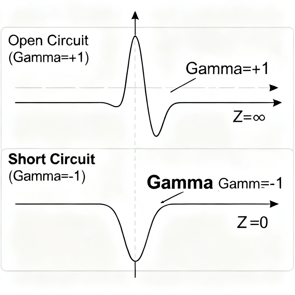
Reflection Coefficient (Γ) for Open Circuit vs Short Circuit
The open circuit vs short circuit reflection in transmission line is governed by the reflection coefficient formula: Γ = (Z_load – Z0) / (Z_load + Z0). For an open circuit, Z_load is infinite, yielding Γ = +1, meaning the reflected voltage is in phase and doubles at the load. For a short circuit, Z_load is zero, yielding Γ = -1, meaning the reflected voltage is inverted and cancels the incident wave at the load.
Open Circuit Reflection: Voltage Doubling
When a transmission line is terminated with an open circuit, the load impedance is infinite. The open circuit vs short circuit reflection in transmission line shows that Γ_open = +1. The incident voltage wave sees the open end, and to satisfy zero current condition, a reflected wave of the same polarity is generated. The total voltage at the open end becomes 2 × V_incident, causing severe overshoot.
Short Circuit Reflection: Voltage Cancellation
When a transmission line is terminated with a short circuit, the load impedance is zero. The open circuit vs short circuit reflection in transmission line shows that Γ_short = -1. The incident voltage wave sees the short end, and to satisfy zero voltage condition, a reflected wave of opposite polarity is generated. The total voltage at the short end becomes zero, while current doubles.
Practical Implications of Open Circuit vs Short Circuit Reflection in Transmission Line
Worst-Case Signal Integrity Issues
The open circuit vs short circuit reflection in transmission line creates worst-case signal integrity problems. Open circuits cause overshoot that can exceed IC absolute maximum ratings, leading to latch-up or reliability damage. Short circuits collapse the signal to zero, causing complete data loss. Both conditions create ringing that persists for multiple clock cycles, increasing EMI and causing timing errors.
Real-World Examples in High-Speed PCB
Open circuit vs short circuit reflection in transmission line occurs in real designs. Open circuits appear as unterminated stubs from vias to pins, loose connectors, or floating inputs. Short circuits appear as solder bridges between signal traces and ground planes, damaged traces, or defective vias shorting to inner layers. These defects cause total reflection and system failure.
Source Impedance and Re-Reflection
The open circuit vs short circuit reflection in transmission line depends on source impedance. If the driver output impedance does not match Z0, the reflected wave re-reflects at the source. For an open load (Γ_load = +1) and low-impedance source (Γ_source ≈ -1), the wave inverts and travels back, creating a resonant cavity with extreme ringing. Proper source termination absorbs the reflected energy.
| Parameter | Open Circuit (Γ = +1) | Short Circuit (Γ = -1) |
|---|---|---|
| Load Impedance | Infinite | Zero |
| Reflected Voltage | In phase, same magnitude | 180° out of phase, same magnitude |
| Voltage at Load | 2 × V_incident (overshoot) | 0 V (collapse) |
| Current at Load | Zero | 2 × I_incident |
| Signal Integrity Impact | Overshoot, ringing, EMI | Data loss, timing errors |
Mitigation Strategies for Open Circuit vs Short Circuit Reflection in Transmission Line
Proper Termination Techniques
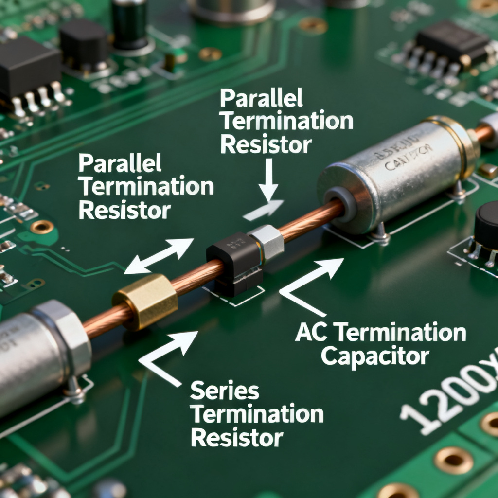
Eliminating open circuit vs short circuit reflection in transmission line requires matching Z_load to Z0. Parallel termination uses a resistor equal to Z0 between signal and ground at the receiver, absorbing all incident energy. Series termination places a resistor at the source so R_s + R_driver = Z0, absorbing the reflected wave. AC termination uses a resistor-capacitor network to block DC while matching high-frequency impedance. Thevenin termination uses two resistors for differential pairs.
Critical PCB Layout Rules
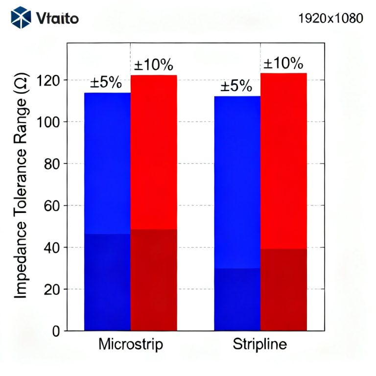
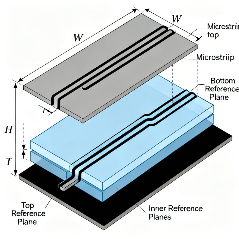
To minimize open circuit vs short circuit reflection in transmission line, avoid stubs longer than 1/10th of the signal rise time. Minimize vias and use microvias or back-drilling to eliminate via stubs. Work with your PCB manufacturer for controlled impedance (e.g., 50Ω single-ended, 100Ω differential). Use a solid ground plane beneath signal layers for low-inductance return paths. For differential pairs, maintain equal length and consistent spacing.
Simulation and Measurement
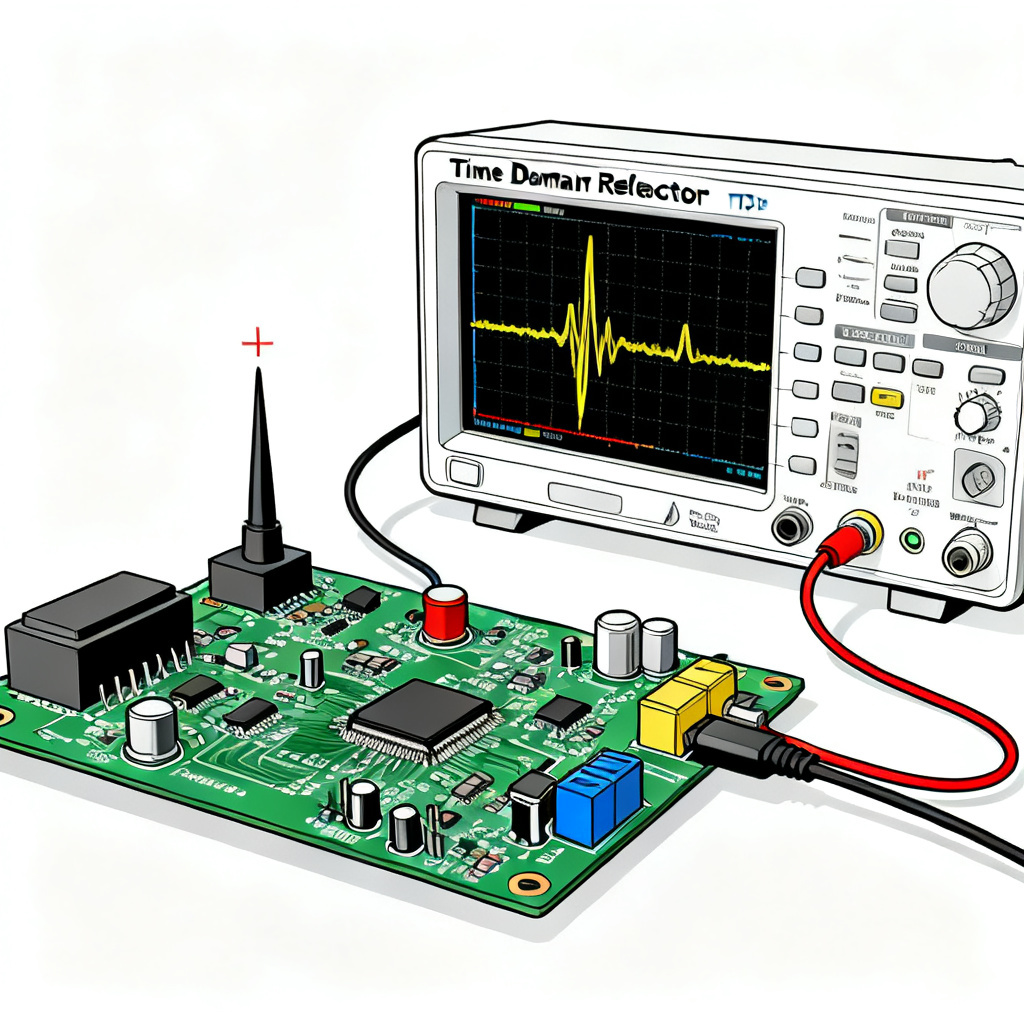
Pre-layout simulation of open circuit vs short circuit reflection in transmission line using tools like HyperLynx, ADS, or Ansys SIwave predicts ringing amplitude. Post-layout TDR simulation sends a fast pulse and measures reflected energy—open circuits appear as positive impedance spikes, short circuits as negative impedance spikes. Real oscilloscope measurement at the receiver confirms overshoot (open circuit) or collapsed voltage (short circuit).
Case Study: Open Circuit vs Short Circuit Reflection in Transmission Line for DDR4
Consider a DDR4 memory bus at 3200 MT/s. If ODT is disabled, the open circuit vs short circuit reflection in transmission line creates a worst-case scenario. The incident 1.2V signal doubles to 2.4V at the open DRAM pin, exceeding the 1.5V absolute maximum rating. This overshoot can latch up the DRAM, and the reflected wave corrupts the next clock cycle. If a manufacturing defect shorts the data line to ground, the signal collapses to 0V, causing complete read failure. Enabling ODT (parallel termination to VDDQ) absorbs the energy, providing a clean 1.2V signal.
FAQ on Open Circuit vs Short Circuit Reflection in Transmission Line
What is the difference between open circuit and short circuit reflection in transmission line?
The open circuit vs short circuit reflection in transmission line differs in reflection coefficient: open circuit gives Γ = +1 (voltage doubles), short circuit gives Γ = -1 (voltage cancels). Open circuits cause overshoot and ringing, while short circuits cause signal collapse and data loss.
How does open circuit vs short circuit reflection in transmission line affect signal integrity?
Open circuit vs short circuit reflection in transmission line creates worst-case reflections with 100% energy return. Open circuits cause voltage doubling and overshoot, while short circuits cause zero voltage and current doubling. Both create ringing, timing errors, and increased EMI.
What termination techniques prevent open circuit vs short circuit reflection in transmission line?
To prevent open circuit vs short circuit reflection in transmission line, use parallel termination (resistor to ground), series termination (resistor at source), AC termination (resistor-capacitor), or Thevenin termination. These match load impedance to Z0, absorbing reflected energy.
Our High-Speed PCB Manufacturing Services
As a B2B high-speed PCB manufacturer, we specialize in eliminating open circuit vs short circuit reflection in transmission line through controlled impedance testing, advanced via technologies (back-drilling, microvias), and expert DFM review for high-speed design rules. Our services include 50Ω and 100Ω impedance control, TDR measurement, and signal integrity verification to ensure your transmission lines are free of reflection issues.