Mastering how to use impedance control PCB calculators like Polar Si9000, Saturn PCB Toolkit, and Altium is essential for high-speed PCB design success. This guide provides a definitive workflow for achieving 50Ω single-ended and 100Ω differential impedance with precision.
Impedance Control Fundamentals for High-Speed PCB Design
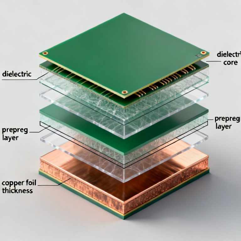
Before using any impedance control PCB calculator, you must understand the transmission line parameters: trace width (W), trace thickness (T), dielectric height (H), dielectric constant (Dk), loss tangent (Df), copper roughness, and solder mask thickness. The two most common models are microstrip (outer layer) and stripline (inner layer). Stripline offers superior EMI isolation for high-speed signals.

How to Use Polar Si9000: The Industry Gold Standard
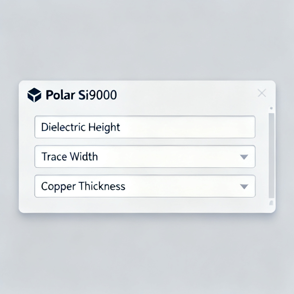
Polar Si9000 uses a 2D boundary element method field solver for ±5% accuracy. This impedance control PCB calculator is the preferred tool for production-ready designs.
Step 1: Select the Correct Model
Choose from Surface Microstrip (1A/2A), Symmetrical Stripline (3A), Asymmetrical Stripline (4A), Differential Edge-Coupled Microstrip (7A), or Differential Edge-Coupled Stripline (8A). Always match the model to your exact stack-up.
Step 2: Enter Physical Parameters
Input H1 (dielectric height after lamination), Er1 (design Dk at operating frequency), W1 and W2 (trapezoidal trace widths), T1 (finished copper thickness), and C1/C2/C3 (solder mask parameters). Ignoring solder mask can cause a 2–4Ω error.
Step 3: Run the Calculation
Click “Calculate” to obtain Z0 (single-ended) or Zdiff (differential), propagation delay, and capacitance per unit length.
Step 4: Optimize by Iteration
If Z0 is too low, increase trace width or decrease dielectric height. For differential pairs, adjust spacing (S) to fine-tune Zdiff.
Step 5: Generate a Report
Export results as PDF or CSV for fabrication documentation. Include the exact model number and all input parameters.
How to Use Saturn PCB Design Toolkit: The Free Versatile Option
The Saturn PCB Toolkit offers a free impedance control PCB calculator with a built-in stack-up editor. It is ideal for quick estimates and educational purposes.
Step 1: Select Impedance Calculator
Choose from Single Ended Microstrip, Single Ended Stripline, Differential Microstrip, Differential Stripline, or Coplanar Waveguide.
Step 2: Enter Stack-Up Parameters
Input Er, trace width (W), trace spacing (S) for differential pairs, dielectric height (H), copper thickness (T), and frequency. Saturn automatically adjusts Dk vs. frequency for FR-4.
Step 3: Use the Solder Mask Feature
Check “Solder Mask on Top” and enter mask thickness and Dk. This rare free feature adjusts impedance by 2–3Ω.
Step 4: Calculate and Review
View Z0, capacitance, inductance, propagation delay, and resistance (Ω/inch). Resistance is unique to Saturn.
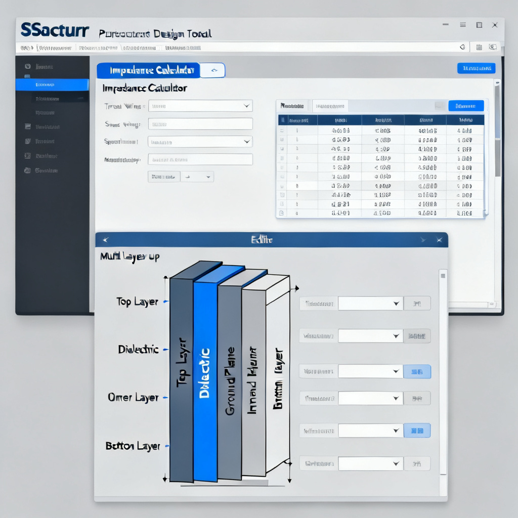
Step 5: Use Stack-Up Editor for Multi-Layer Projects
Define all layers (up to 40) with material, thickness, and Dk. The calculator automatically reads the relevant H value.
Step 6: Export to Fabrication Note
Generate a text summary of stack-up and impedance requirements.
Other Online Impedance Calculators: Altium, AWR, and Web Tools
Altium Designer Built-In Impedance Calculator
Altium’s Layer Stack Manager uses a 2D field solver integrated into the PCB layout. Enable “Impedance Calculation,” define your stack-up, and set the target impedance. Altium dynamically calculates trace width. It requires the Signal Integrity extension (paid).
AWR Microwave Office (Cadence AWR)
AWR is a 3D planar EM solver for designs above 1 GHz. Create a transmission line model, set material properties (Dk, Df, roughness), and run an EM simulation to extract S-parameters and frequency-dependent impedance. Accurate to <1% for 10+ GHz designs.
Free Web-Based Calculators (JLCPCB, PCBWay, DigiKey)
These zero-install tools are tailored to specific manufacturer stack-ups. Select your manufacturer, choose a standard stack-up, and enter target impedance. Results are only valid for the manufacturer’s standard materials.

Comparison Table: Impedance Control PCB Calculators
| Feature | Polar Si9000 | Saturn PCB Toolkit | Altium/AWR | Free Web Tools |
|---|---|---|---|---|
| Accuracy | ±5% (industry standard) | ±10% (good for estimates) | ±2% (AWR), ±5% (Altium) | ±15% (varies by manufacturer) |
| Model Types | 100+ models (coplanar, differential, asymmetrical) | 10 models (basic microstrip/stripline) | 20+ models (Altium), unlimited (AWR) | 5–10 models (microstrip only) |
| Frequency Dependence | Manual Dk entry | Built-in Dk vs. frequency | Full EM simulation (AWR) | None |
| Solder Mask | Yes, detailed | Yes, simplified | Yes (Altium) | No |
| Copper Roughness | Yes (advanced models) | No | Yes (AWR) | No |
| Ease of Use | Moderate (requires training) | Easy (intuitive GUI) | Hard (AWR), Moderate (Altium) | Very Easy |
| Cost | Paid ($1,000–$5,000) | Free | Included in Altium license; AWR is expensive | Free |
| Best For | Production-ready designs, complex stack-ups | Quick estimates, education, small projects | RF/mmWave designs (AWR), integrated workflow (Altium) | Prototyping with specific manufacturers |
Expert Tips for Accurate Impedance Calculation
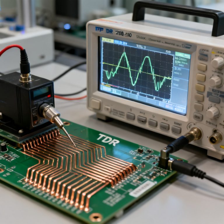
1. Always use the manufacturer’s Dk data at your operating frequency. 2. Account for etching by setting W1 0.5–1 mil narrower than W2 in Polar Si9000. 3. Don’t forget solder mask—add 0.5–1 mil to trace width if your calculator ignores it. 4. For differential pairs, use S = 2W for 100Ω differential impedance. 5. Simulate the entire path, including vias and connectors. 6. Request impedance coupons on your panel for TDR verification.
FAQ: Impedance Control PCB Calculators
What is the most accurate impedance control PCB calculator?
Polar Si9000 is the industry gold standard with ±5% accuracy. For RF/mmWave designs above 10 GHz, AWR’s full-wave EM simulation provides <1% accuracy.
Can I use a free impedance control PCB calculator for production?
Free tools like Saturn PCB Toolkit are suitable for quick estimates and education. For production, always cross-check with Polar Si9000 or a manufacturer-approved calculator.
How does solder mask affect impedance control PCB calculations?
Solder mask lowers impedance by 2–3Ω. Professional calculators like Polar Si9000 and Saturn PCB Toolkit include solder mask parameters to account for this effect.
What is the difference between microstrip and stripline in impedance control?
Microstrip is on an outer layer with one reference plane; stripline is between two reference planes. Stripline offers better EMI isolation and is preferred for high-speed signals.
How do I choose between Polar Si9000 and Saturn PCB Toolkit?
Use Polar Si9000 for production-ready, complex stack-ups. Use Saturn PCB Toolkit for quick estimates, educational purposes, and multi-layer stack-up planning.
```