Crosstalk coupling length analysis is the cornerstone of signal integrity in high-speed PCB design. This guide provides a professional workflow to set up and perform coupling length analysis in your EDA tool, covering everything from defining critical length to interpreting simulation results.
Understanding Crosstalk Coupling Length – The Physics Behind the Setup
Before touching the EDA tool, you must understand what coupling length means in the context of signal integrity. Crosstalk arises from mutual inductance (Lm) and mutual capacitance (Cm) between adjacent traces. The coupling length is the physical distance over which two conductors run in parallel. In a typical microstrip or stripline configuration, the coupled energy increases linearly with length until the line becomes electrically long relative to the signal’s rise time (Tr).
Saturation Length in Crosstalk Analysis
The saturation length is the distance at which the crosstalk noise reaches its maximum value (typically ~1/4 of the signal’s wavelength at the highest frequency component). Beyond this length, the crosstalk does not increase—it saturates. For a 1ns rise time signal on FR4 (Er~4.2), the saturation length is roughly 3-4 inches. For a 100ps rise time (common in 10G+ designs), it drops to ~0.3 inches.
Crosstalk coupling length analysis matters because if your coupling length is shorter than the saturation length, crosstalk is length-dependent and can be mitigated by shortening the parallel run. If your coupling length exceeds the saturation length, the crosstalk is already at its worst-case value; further length increases won’t worsen it, but you must use spacing or shielding. The EDA tool must calculate the coupling length accurately because it directly affects the simulated crosstalk magnitude.
Step-by-Step Setup of Crosstalk Coupling Length Analysis
Step 1: Define the Network and Aggressor/Victim Pairs
In your EDA tool, the first step in crosstalk coupling length analysis is to identify which nets are aggressors (driven by a switching signal) and which are victims (sensitive, high-impedance, or clock nets). This is done in the Signal Integrity (SI) or Crosstalk Analysis workspace.
- Altium Designer: Use the Crosstalk Setup dialog. Select the victim net first, then assign aggressor nets. The tool automatically computes the coupling length based on the physical layout.
- Cadence Allegro: Use the Crosstalk Analysis option under Simulation → SI Analysis. Define the Aggressor Net and Victim Net pairs. The coupling length is extracted from the database.
- Mentor PADS: In the HyperLynx SI tool, use the Crosstalk Wizard. Select the victim trace, then choose the aggressor traces from the layout. The coupling length is displayed in the Coupled Length column.
Critical Setting: Ensure you have enabled Coupled Line Modeling or Multi-Conductor Transmission Line (MTL) modeling in your simulation profile. Without this, the tool treats traces as isolated and ignores coupling.
Step 2: Set the Frequency or Rise Time (Tr) Parameter
The coupling length analysis is only meaningful when the tool knows the signal’s frequency content. Set the rise time (Tr) or the operating frequency of the aggressor signal. The coupling length threshold (saturation length) is a function of Tr. A 100ps rise time will have a much shorter saturation length than a 1ns rise time.
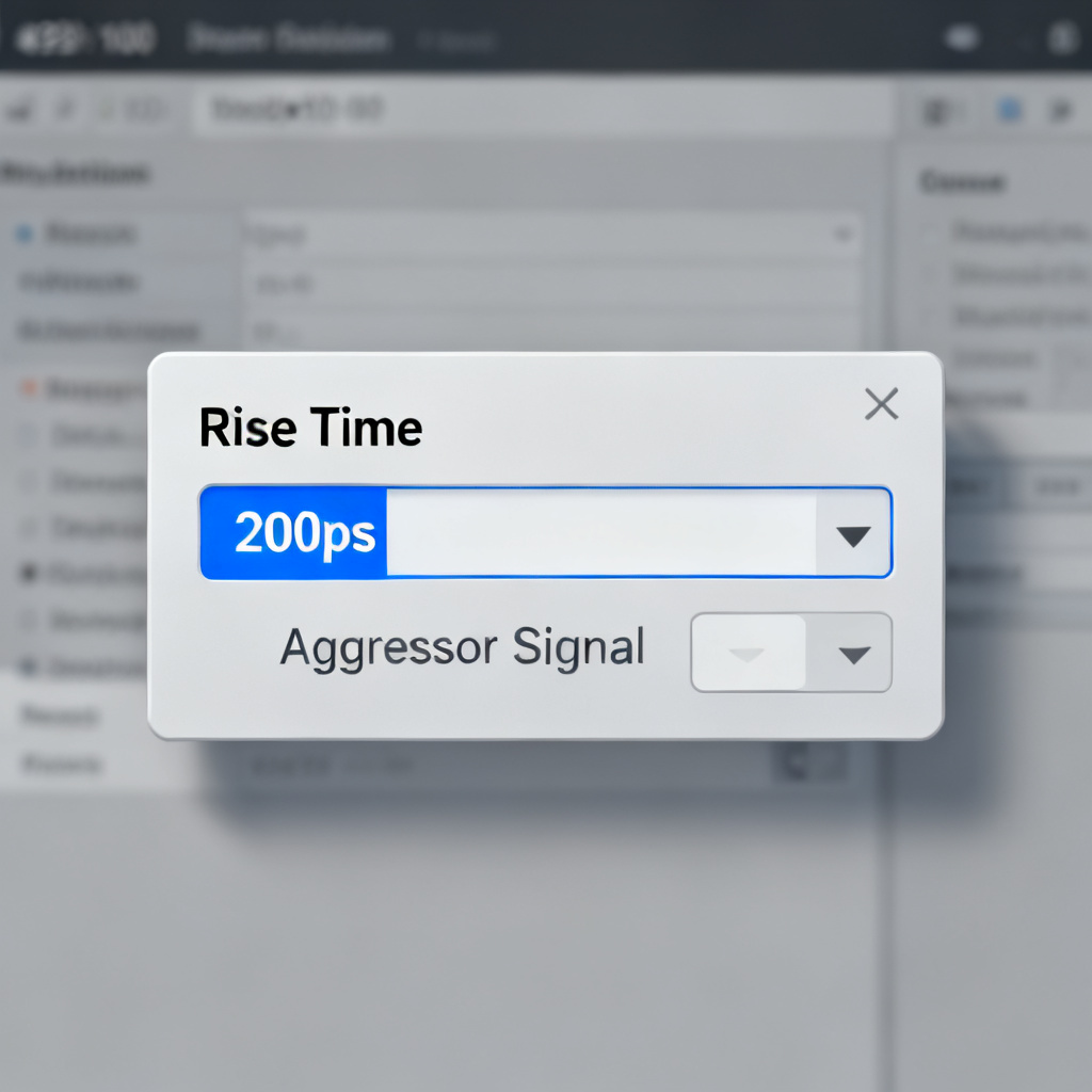
- In Altium: Under Simulation → SI Setup → Advanced, set the Rise Time for the aggressor driver (e.g., 200ps).
- In Allegro: In the SI Model Assignment dialog, assign a driver model (IBIS or SPICE) and set the Transition Time parameter.
- In PADS HyperLynx: In the Crosstalk Wizard, select the driver model and set the Rise Time in the Signal Parameters tab.
Pro Tip: For worst-case analysis, use the fastest rise time the driver can produce (e.g., 20%-80% of the signal swing). This yields the shortest saturation length and the most conservative coupling length requirement.
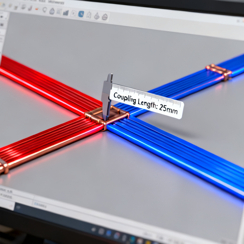
Step 3: Extract the Coupling Length from the Layout
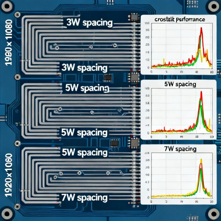
The EDA tool will automatically compute the coupling length for each aggressor-victim pair based on the routed geometry. However, you must verify that the tool’s extraction is accurate. The coupling length is the parallel run distance where the two traces are within a defined spacing threshold (e.g., 3x the dielectric height, or 5 mils for tight coupling).
- In Altium: After running a crosstalk simulation, check the Crosstalk Results table. It lists each aggressor-victim pair with Length (mm).
- In Allegro: Use the Show Coupling command (under Route → Analyze → Show Coupling). It highlights the coupled segments and reports the total coupled length.
- In PADS HyperLynx: The Crosstalk Wizard displays a Coupled Length value in the summary grid.
Troubleshooting: If the coupling length appears zero or very small, check the spacing between traces (too wide? The tool might ignore them), the layer stackup (traces on different reference planes may not couple), or the Coupling Threshold setting (usually 3-5x the trace width; increase it if needed).
Step 4: Run the Crosstalk Simulation (Time Domain or Frequency Domain)
Now, run the actual crosstalk simulation. You have two primary options: Time-Domain (TD) Analysis or Frequency-Domain (FD) Analysis.
Option A: Time-Domain (TD) Analysis
- What it does: Simulates the aggressor switching (e.g., a 1V step with a 200ps rise time) and measures the noise induced on the victim net.
- Result: A waveform showing the near-end crosstalk (NEXT) and far-end crosstalk (FEXT) noise voltage over time.
- When to use: For digital signals where rise time and noise margin are critical.
- Setup: In Altium, run Crosstalk Simulation from the SI menu. Select Time Domain and set the simulation time (e.g., 5ns). In Allegro, use Simulation → Crosstalk → Run Crosstalk. Choose Transient analysis. In PADS HyperLynx, click Run Crosstalk Simulation in the wizard. Select Time Domain and set the Simulation Stop Time.
Option B: Frequency-Domain (FD) Analysis
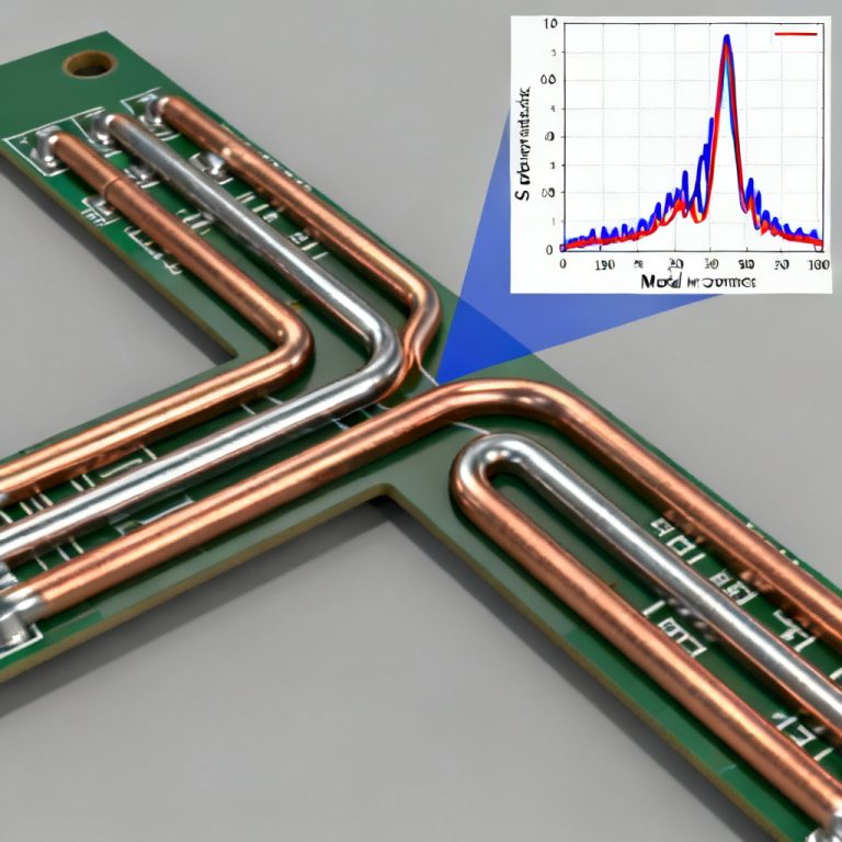
- What it does: Calculates the S-parameters or crosstalk transfer function (S31 or S41) as a function of frequency.
- Result: A plot of crosstalk magnitude (in dB) vs. frequency, showing resonance peaks where coupling is worst.
- When to use: For RF or high-speed analog signals where frequency-dependent coupling matters.
- Setup: In Allegro, use Simulation → S-Parameter Extraction and select the aggressor/victim ports. In PADS HyperLynx, use the Frequency Domain tab in the crosstalk wizard.
Critical Insight: The coupling length directly affects the FEXT magnitude in time-domain analysis. FEXT is proportional to the derivative of the signal (dV/dt) and the coupling length (L). For long coupling lengths, FEXT can become a differential-mode noise source.
Step 5: Interpret the Results – Coupling Length vs. Crosstalk
Once the simulation is complete, analyze the results to determine if the coupling length is acceptable.
Key Metrics to Check:
- Peak Crosstalk Voltage (NEXT/FEXT): Compare to the victim’s noise margin (e.g., < 5% of Vdd for high-speed logic).
- Crosstalk vs. Coupling Length Sweep: Many EDA tools allow you to sweep the coupling length (by changing trace length or spacing) and see the crosstalk trend. In Altium, use Parametric Sweep and set the Trace Length as the parameter. In Allegro, use Optimization with Coupling Length as the variable.
- Saturation Check: If the crosstalk does not increase when you double the coupling length, you have reached saturation. In this case, you must increase spacing or add guard traces.
Example Interpretation (from a real simulation):
- For a 1ns rise time, 6-inch coupling length, 5-mil spacing on a 4-layer stackup: NEXT = 120mV, FEXT = 80mV.
- For a 0.5ns rise time, same conditions: NEXT = 240mV, FEXT = 160mV (double!).
- Action: Reduce coupling length to < 3 inches or increase spacing to 10 mils.
Advanced Setup Techniques for Accurate Coupling Length Analysis
Technique 1: Use 3D Field Solvers for Non-Ideal Geometries
Standard 2D field solvers (used in most EDA tools) assume uniform cross-sections. For real-world boards with bends, vias, or non-uniform spacing, use a 3D solver like Ansys HFSS or CST integrated with your EDA tool. Export the layout of the coupled region (aggressor + victim + reference plane) as a DXF or GDS file. Import into the 3D solver. Define ports at the aggressor driver and victim receiver. Run a frequency sweep (DC to 20 GHz for 10G signals). Compare the S-parameter results (S31 = crosstalk) with your 2D EDA tool results. Crosstalk coupling length analysis using 3D solvers captures edge coupling and via-to-via coupling, which can add 10-20% more crosstalk than a simple 2D model predicts.

Technique 2: Incorporate Manufacturing Tolerances
Coupling length analysis is only as good as your manufacturing assumptions. Use statistical analysis (Monte Carlo) to account for etch variation (trace width ±10%), dielectric thickness variation (prepreg thickness ±15%), and misregistration (trace spacing tolerance ±0.5 mils). In Cadence Allegro, use Statistical Analysis under SI Analysis → Monte Carlo. Set the coupling length as a parameter with a Gaussian distribution (mean = routed length, sigma = 10%). In Mentor HyperLynx, use Advanced Analysis → Statistical and define the coupling length’s tolerance.
Technique 3: Optimize Coupling Length with Guard Traces
If the coupling length is too long and cannot be shortened, a guard trace (a grounded trace between aggressor and victim) can reduce crosstalk by 10-20 dB. However, the guard trace must be properly stitched to ground with vias at every λ/20 (e.g., every 1.5mm for 10 GHz). Add a guard trace in your layout. In the EDA tool, define the guard trace as a Shield Net (ground). Run the same crosstalk simulation. Compare the crosstalk magnitude with and without the guard trace. The guard trace’s effectiveness depends on its coupling length to the aggressor. If the guard trace runs parallel to the aggressor for the same length, it will couple strongly to the aggressor and then re-radiate to the victim. The guard trace must be short or have a high inductance to ground (i.e., many vias).
Common Pitfalls and How to Avoid Them
| Pitfall | Cause | Solution |
|---|---|---|
| Zero coupling length reported | The coupling threshold (spacing) is too strict | Reduce the Coupling Threshold to 2x trace width |
| Crosstalk simulation fails | Missing IBIS model or incorrect net assignment | Double-check that both aggressor and victim have valid models |
| FEXT is negative | The victim is longer than the aggressor, causing odd-mode cancellation | Check the length difference; ensure the victim is not longer than the aggressor by more than 20% |
| Simulation results don’t match measurement | The EDA tool uses 2D field solver; real board has 3D effects | Use a 3D solver for critical nets (clock, data lines > 5 Gbps) |
Integrating Coupling Length Analysis into Your Design Flow
To make crosstalk coupling length analysis a routine part of your high-speed PCB design, follow this workflow:
- Pre-Layout Planning: Define maximum allowed coupling length based on rise time and noise margin. Use the formula: L_max = (Tr * v) / 4 where v is the propagation velocity (e.g., 6 inches/ns for FR4). For a 200ps rise time, L_max ≈ 0.3 inches.
- During Routing: Use the EDA tool’s real-time coupling length monitor (e.g., Altium’s Crosstalk Length rule in the PCB Rules Editor). Set a design rule: CouplingLength <= L_max.
- Post-Routing Verification: Run the full crosstalk simulation as described in Section 2. If any pair exceeds the noise margin, shorten the coupling length or add guard traces.
- Manufacturing Handoff: Include the coupling length analysis report in your design documentation. This helps the fabrication team understand critical areas.
Frequently Asked Questions About Crosstalk Coupling Length Analysis
What is crosstalk coupling length analysis?
Crosstalk coupling length analysis is the process of measuring and simulating the parallel run distance between aggressor and victim traces in a PCB to predict and mitigate signal integrity issues in high-speed designs.
Why is coupling length critical in high-speed PCB design?
Coupling length directly determines the amount of capacitive and inductive crosstalk. Longer coupling lengths increase noise until saturation, potentially causing false triggering or jitter in high-speed signals.
How do I set up coupling length analysis in Altium Designer?
In Altium Designer, use the Crosstalk Setup dialog to select victim and aggressor nets, set the rise time, and run a time-domain simulation. The tool automatically computes the coupling length from the layout.
What is the difference between NEXT and FEXT in coupling length analysis?
NEXT (Near-End Crosstalk) is noise measured at the aggressor’s driver end, while FEXT (Far-End Crosstalk) is noise at the victim’s receiver end. FEXT is more sensitive to coupling length and signal rise time.
Can guard traces eliminate crosstalk entirely?
Guard traces can reduce crosstalk by 10-20 dB but require proper grounding with vias at every λ/20. They do not eliminate crosstalk entirely but are effective for reducing coupling in critical high-speed nets.
Conclusion: Mastering Coupling Length for Reliable High-Speed Designs
Setting up crosstalk coupling length analysis in your EDA tool is not a one-time task—it is a skill that evolves with your design complexity. By following the steps outlined here—defining aggressor/victim pairs, setting rise time, extracting coupling length, running time- or frequency-domain simulations, and interpreting results—you can systematically eliminate crosstalk-induced failures. For high-speed PCB designs (10 Gbps and above), coupling length analysis is as critical as impedance control. Use the advanced techniques (3D solvers, statistical analysis, guard traces) to push your designs to the next level. Remember: the goal is not just to meet the noise margin, but to design with margin that accounts for manufacturing variation and aging.
Ready to optimize your next design? Start by running a coupling length analysis on your most critical clock or data bus. The results will surprise you.
About the Author: This guide is brought to you by [Your Company Name], a leading provider of high-speed PCB manufacturing and assembly services. We specialize in designs with controlled impedance, tight coupling control, and advanced signal integrity analysis. Contact us for a free design review.