Master Excel-Based Crosstalk Estimation for High Speed PCB with a practical, transparent calculator you can build today. This guide provides closed-form equations, step-by-step implementation, and real-world validation for near-end and far-end crosstalk prediction.
Why Excel for High Speed PCB Crosstalk Estimation?
Excel-Based Crosstalk Estimation for High Speed PCB offers speed, accessibility, and full transparency—no costly licenses, no complex setups. You can iterate quickly on spacing, dielectric thickness, and rise time, making it ideal for early-stage feasibility studies and design reviews.
- Speed and accessibility: Open Excel, enter parameters, get instant results.
- Transparency: Every formula is visible; you understand the physics behind the numbers.
- Iterative design: Test “what-if” scenarios without re-running expensive simulations.
- Education and communication: A perfect tool to teach crosstalk fundamentals to junior engineers.
Limitation: Excel-based estimation uses closed-form analytical equations, accurate for simple 2D cross-sections but not for 3D effects (bends, vias, connectors). Always validate with a 3D field solver for final sign-off.
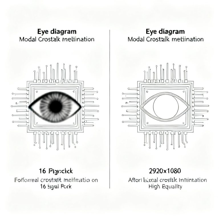
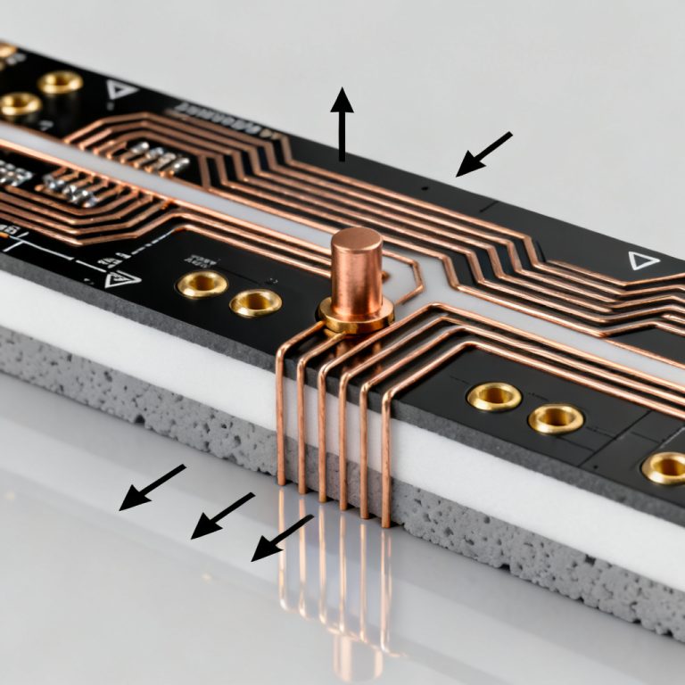
Crosstalk Physics for High Speed PCB
Understanding the physics is essential for Excel-Based Crosstalk Estimation for High Speed PCB. Crosstalk occurs when electromagnetic fields from an aggressor trace couple into a victim trace via capacitive and inductive coupling.
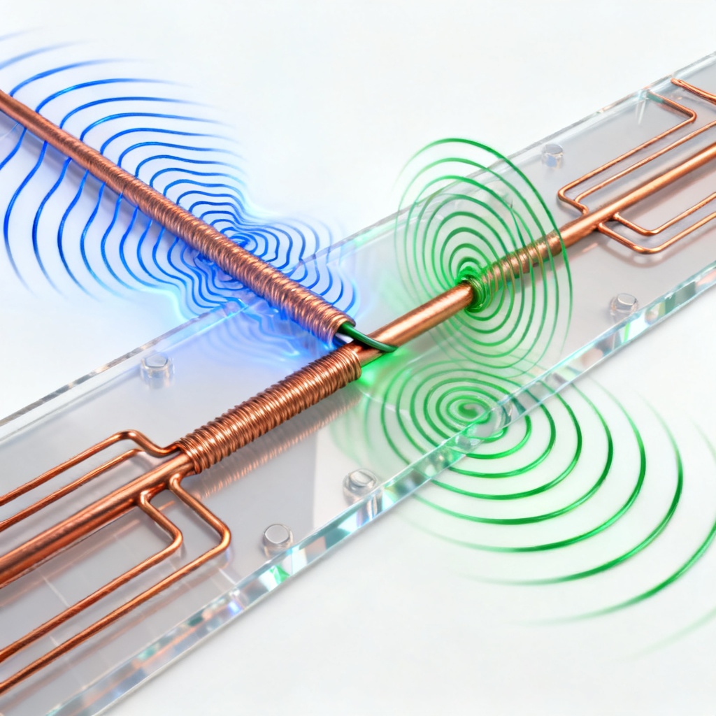
- Capacitive coupling (C): Electric field between adjacent traces injects current into the victim line.
- Inductive coupling (L): Magnetic field induces voltage in the victim line.
These produce two noise types:
- Near-End Crosstalk (NEXT): Measured at the victim end nearest the aggressor driver. Pulse width equals twice the propagation delay of the coupled length.
- Far-End Crosstalk (FEXT): Measured at the far end. Sensitive to the difference between capacitive and inductive coupling. In microstrips, FEXT can be significant; in striplines, ideally zero.
Core Equations for Your High Speed PCB Crosstalk Calculator
We use the odd-mode and even-mode impedance method, the industry standard for coupled transmission lines, based on IPC-2141A and Howard Johnson & Martin Graham.
Step 1: Single-Line Characteristics (Without Coupling)
For a microstrip (trace on outer layer):
- Effective Dielectric Constant (εr_eff): εr_eff = (εr + 1)/2 + (εr – 1)/2 * 1/√(1 + 12 * H/W)
- Characteristic Impedance (Z0): Z0 = 87/√(εr + 1.41) * ln(5.98 * H / (0.8 * W + T))
For a stripline (trace on inner layer):
- εr_eff = εr
- Characteristic Impedance (Z0): Z0 = 60/√(εr) * ln(4 * H / (0.67 * π * (0.8 * W + T)))
Step 2: Odd and Even Mode Impedances (With Coupling)
For microstrip (using IPC-2251 / Howard Johnson):
- Zodd = Z0 * √(1 – 0.48 * e^(-0.96 * S/H)) / √(1 + 0.48 * e^(-0.96 * S/H))
- Zeven = Z0 * √(1 + 0.48 * e^(-0.96 * S/H)) / √(1 – 0.48 * e^(-0.96 * S/H))
For stripline:
- Zodd = Z0 * √(1 – 0.374 * e^(-2.9 * S/H)) / √(1 + 0.374 * e^(-2.9 * S/H))
- Zeven = Z0 * √(1 + 0.374 * e^(-2.9 * S/H)) / √(1 + 0.374 * e^(-2.9 * S/H))
Step 3: Inductive and Capacitive Coupling Coefficients
Using Zodd, Zeven, and speed of light (c = 3e8 m/s):
- Mutual Inductance (Lm): Lm = (Zeven – Zodd)/2 * √(εr_eff)/c
- Mutual Capacitance (Cm): Cm = (Zeven – Zodd)/(2 * Zodd * Zeven) * √(εr_eff)/c
Step 4: Calculate NEXT and FEXT Voltages
Assume aggressor has voltage swing Vin and rise time tr, coupled length L_coup.
- Near-End Crosstalk (NEXT) Voltage: VNEXT = 1/4 * ((Zeven – Zodd)/(Zeven + Zodd)) * Vin
- Critical length L_crit = tr / (2 * τpd)
- For L_coup < L_crit: VNEXT_peak = VNEXT_sat * (2 * L_coup / L_crit)
- Far-End Crosstalk (FEXT) Voltage: VFEXT = –1/2 * (L_coup/tr) * ((Zeven – Zodd)/(Zeven + Zodd)) * (√(εr_eff)/c) * Vin
Key insight: In stripline, FEXT is theoretically zero; in microstrip, it can be significant.
Building Your High Speed PCB Crosstalk Calculator in Excel
Follow this structured approach to create your own Excel-Based Crosstalk Estimation for High Speed PCB tool.
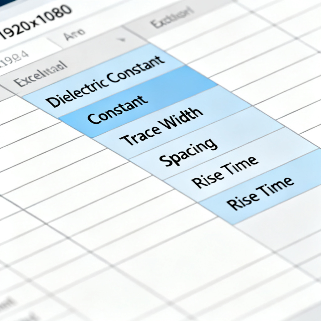
Worksheet 1: Input Parameters
| Parameter | Symbol | Unit | Typical Value |
|---|---|---|---|
| Dielectric Constant | εr | – | 4.5 (FR4) |
| Dielectric Thickness | H | mm | 0.2 |
| Trace Width | W | mm | 0.15 |
| Trace Thickness | T | μm | 35 (1 oz Cu) |
| Trace Spacing (Edge-to-Edge) | S | mm | 0.15 |
| Coupled Length | L_coup | mm | 50 |
| Rise Time (10%-90%) | t_r | ps | 100 |
| Input Voltage Swing | V_in | V | 3.3 |
| Layer Type | – | – | Microstrip or Stripline |
Worksheet 2: Calculations (Hidden or Protected)
Implement formulas from Steps 1–4 using named ranges. Example for microstrip:
- εr_eff: =(εr+1)/2+(εr-1)/2*(1/SQRT(1+12*H/W))
- Z0: =87/SQRT(εr+1.41)*LN(5.98*H/(0.8*W+T))
- Coupling coefficient (k): =0.48*EXP(-0.96*S/H)
- Zodd: =Z0*SQRT((1-k)/(1+k))
- Zeven: =Z0*SQRT((1+k)/(1-k))
- NEXT_sat: =0.25*((Zeven-Zodd)/(Zeven+Zodd))*V_in
- τpd: =SQRT(εr_eff)/3E8*1E12 (ps/mm)
- L_crit: =t_r/(2*τpd)
- NEXT_peak: =IF(L_coup<L_crit, NEXT_sat*2*L_coup/L_crit, NEXT_sat)
- FEXT: =-0.5*(L_coup/t_r)*((Zeven-Zodd)/(Zeven+Zodd))*τpd*V_in
Worksheet 3: Results Dashboard
| Output | Value | Unit |
|---|---|---|
| Single-line Impedance (Z0) | … | Ohms |
| Odd-mode Impedance (Zodd) | … | Ohms |
| Even-mode Impedance (Zeven) | … | Ohms |
| Critical Length (Lcrit) | … | mm |
| NEXT (Peak or Saturated) | … | mV |
| FEXT | … | mV |
| NEXT as % of V_in | … | % |
| FEXT as % of V_in | … | % |
Advanced Considerations for High Speed PCB Crosstalk
Enhance your Excel-Based Crosstalk Estimation for High Speed PCB with these advanced factors.
- Frequency dependence: Include skin effect and dielectric loss for higher frequencies using lookup tables.
- Multiple aggressors: Use superposition—NEXT_total = √(Σ NEXT_i²) for uncorrelated noise; FEXT_total = Σ FEXT_i for correlated.
- Differential crosstalk: Estimate using odd-mode impedance (Z_diff = 2 * Zodd) and calculate between differential pairs.
- Guard traces and stitching vias: Approximate by increasing effective spacing (S) by 30–50% or applying a reduction factor of 0.5–0.7 on the coupling coefficient.
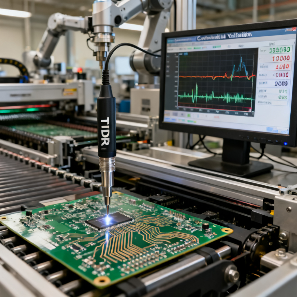
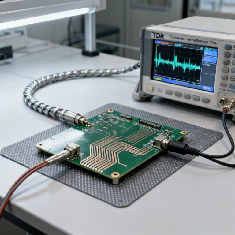
Validation of Your High Speed PCB Crosstalk Calculator
Validate your Excel-Based Crosstalk Estimation for High Speed PCB against industry standards.
- IPC-2141A Nomographs: Match Zodd and Zeven within 5–10%.
- Free online calculators: Use community tools from edaboard.com or si-list.com as sanity checks.
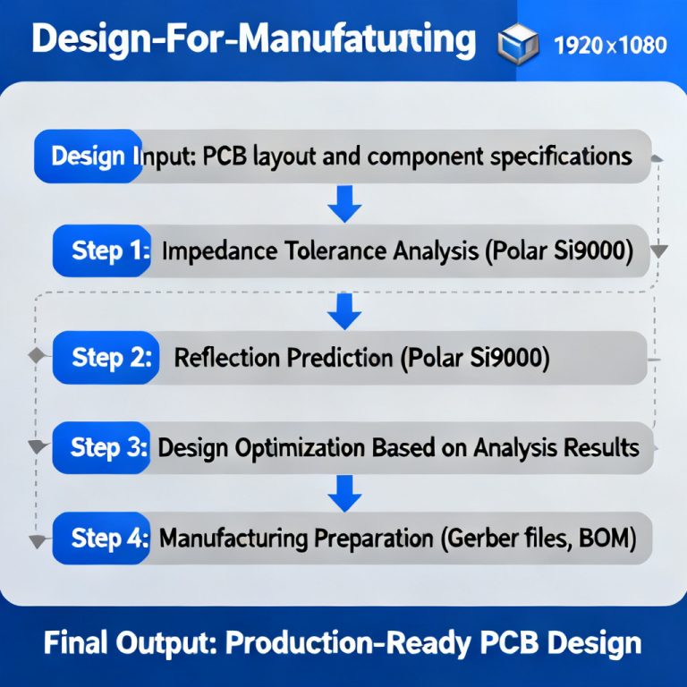
- Field solver (e.g., Polar Si9000, HyperLynx): Expect discrepancies of 10–20% for microstrip, <10% for stripline.
Common error sources: Ignoring trace thickness, using wrong εr (FR4 varies 4.2–4.8), assuming homogeneous medium for microstrip.
Practical Application for High Speed PCB Design
Use your calculator to optimize High Speed PCB designs. Example: DDR3 bus (800 MHz, 1.5V) on Layer 1 microstrip, 50Ω single-ended, 0.1mm width, 0.1mm spacing, 0.2mm dielectric, 50mm coupled length, 100ps rise time.
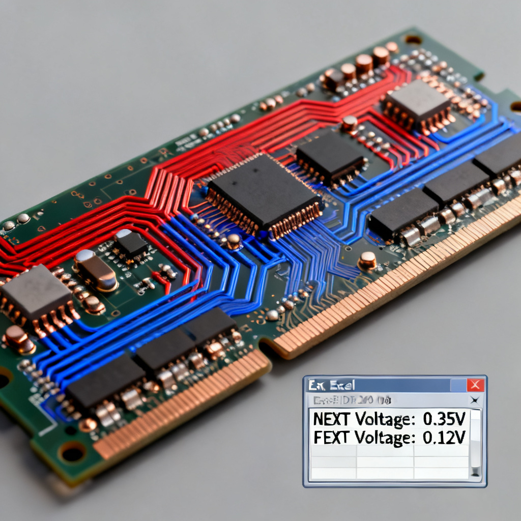
- Z0 = 51.2Ω, Zodd = 42.1Ω, Zeven = 62.3Ω
- NEXT_sat = 72.4 mV (4.8% of V_in)
- L_crit = 7.46 mm → L_coup > L_crit, so NEXT = 72.4 mV
- FEXT = –0.485 V (32.3% of V_in) — dangerously high!
Action: Increase spacing to 0.2mm, reduce coupled length, move to stripline, or add guard traces. Your calculator enables rapid “what-if” analysis.
FAQ: Excel-Based Crosstalk Estimation for High Speed PCB
What is the accuracy of Excel-Based Crosstalk Estimation for High Speed PCB?
Can I use Excel-Based Crosstalk Estimation for High Speed PCB with differential pairs?
How do I handle multiple aggressors in Excel-Based Crosstalk Estimation for High Speed PCB?
Conclusion: From Estimation to Manufacturing
An Excel-Based Crosstalk Estimation for High Speed PCB calculator is an indispensable first-pass tool. It empowers you to make quick, informed decisions during layout, communicate risks with quantitative data, and reduce costly prototype spins. Our company combines these analytical techniques with advanced manufacturing capabilities—producing high-quality, high-speed PCBs with precise impedance control and rigorous SI testing. Download our free Excel template or contact our engineering team for a custom SI analysis.