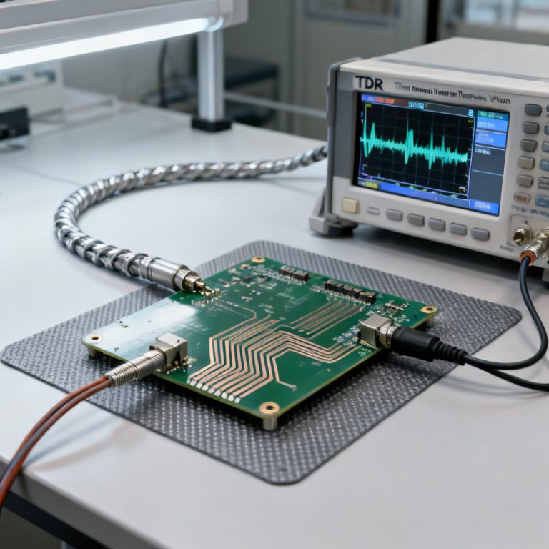
Measuring power rail ripple and noise with an oscilloscope is essential for high-speed PCB validation. This guide covers probe selection, bandwidth limits, and measurement techniques to ensure accurate results in B2B PCB manufacturing.
1. Understanding Power Rail Ripple vs. Noise
Before measuring power rail ripple and noise, distinguish between ripple and noise. Ripple is periodic, low-frequency (50–100 kHz) from switching regulators. Noise is high-frequency, random (>100 MHz) from digital switching or crosstalk. Both degrade signal integrity in high-speed PCBs.
2. Essential Oscilloscope and Probe Setup for Power Rail Ripple and Noise
2.1 Oscilloscope Requirements
For accurate power rail ripple and noise measurements, oscilloscope bandwidth must be at least 5× the highest frequency. For ripple (100 kHz), 20 MHz suffices. For noise (500 MHz), use 1 GHz or higher. Enable high-resolution mode (12-bit) for millivolt levels. Sampling rate should be 2.5× bandwidth.
2.2 Probe Selection and Technique
Best option: 50 Ω coaxial cable with DC blocking. Use a short SMA/BNC cable connected to the scope’s 50 Ω input. Add a 0.1 µF DC blocking capacitor to protect the scope. This minimizes noise pickup for power rail ripple and noise measurement.
Second option: Passive 10× probe. Use a 10× probe (500 MHz) with spring ground clip—not long ground lead. Set probe to 1× for higher sensitivity. For 10×, ensure 1 MΩ input.
Third option: Active differential probe. Ideal for floating measurements. Use low-noise active probe with high CMRR.
Critical tip: Always use a short ground connection—ground spring or coaxial tip. A 6-inch ground lead adds 20–30 mV noise at 100 MHz.
3. Step-by-Step Measurement Procedure for Power Rail Ripple and Noise
3.1 Configure the Oscilloscope
Set input impedance to 50 Ω for coaxial cable, 1 MΩ for passive probes. Use AC coupling to block DC and amplify ripple/noise. Enable 20 MHz bandwidth limiter for ripple-only; disable for full noise. Set timebase: 10–20 µs/div for ripple, 1–10 ns/div for noise.
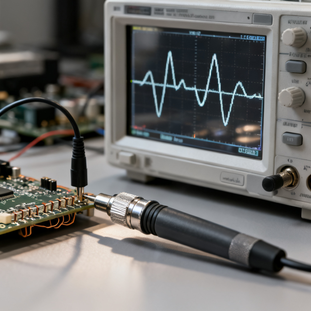
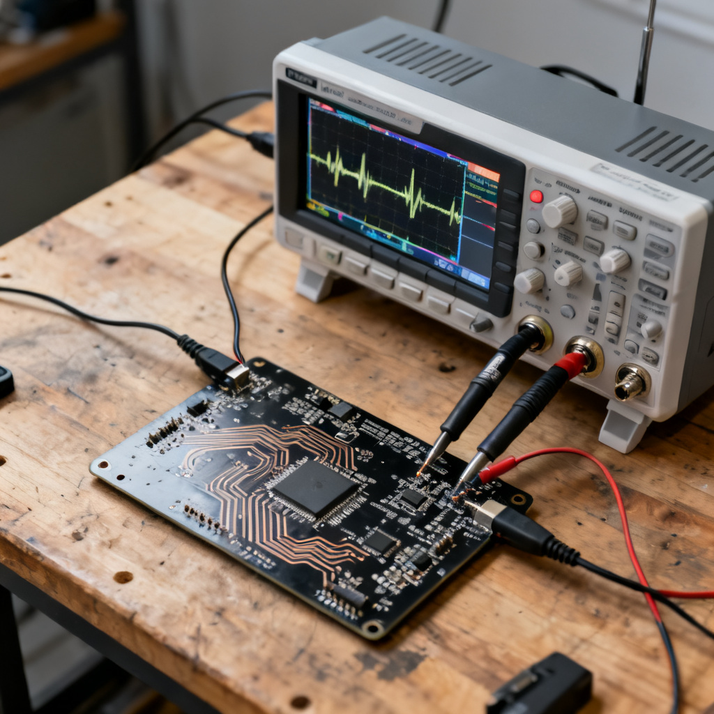
3.2 Connect the Probe
Probe directly at the output capacitor of the voltage regulator—the bulk capacitor at the load. Use shortest ground path: ground spring or adjacent via. Avoid probing at connectors or far from load; PCB trace impedance adds noise.
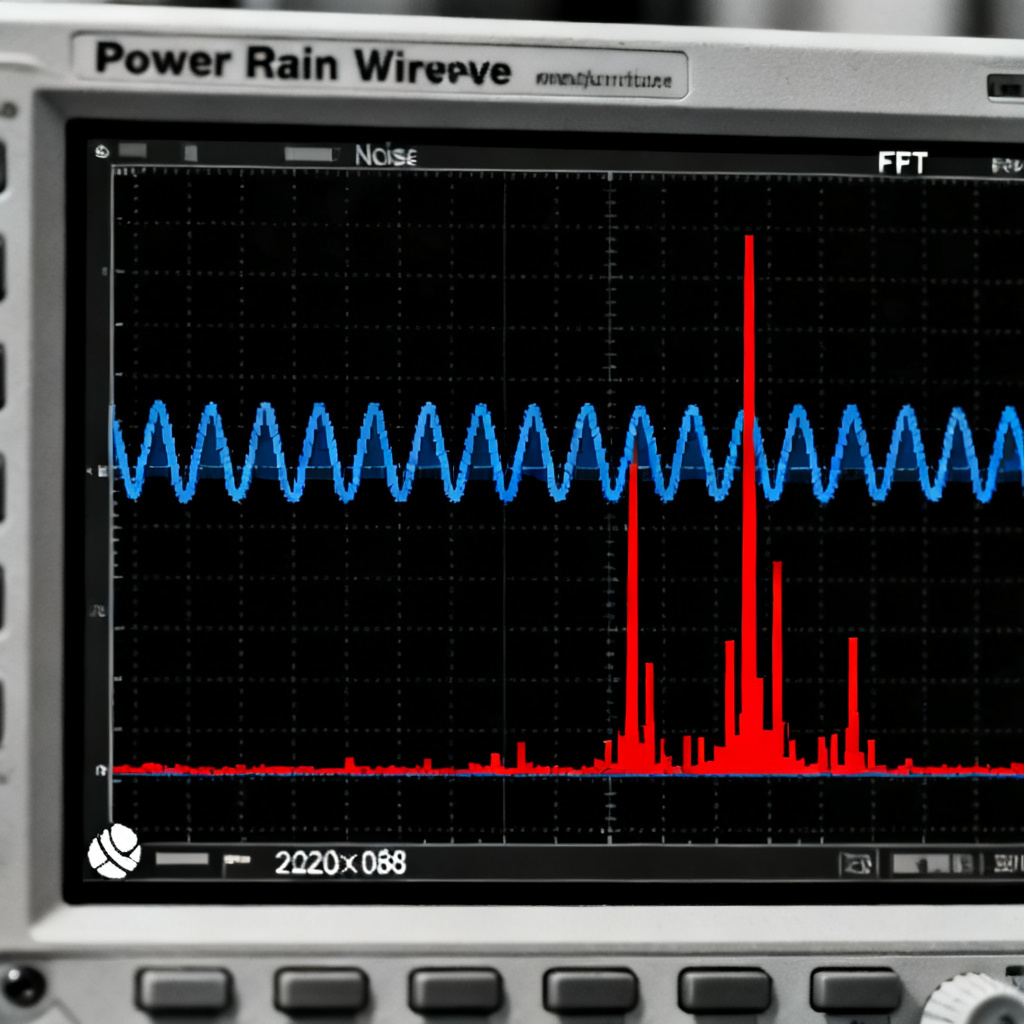
3.3 Acquire and Analyze the Waveform
Start at 50 mV/div, decrease to 5–10 mV/div. Use edge trigger for periodic ripple; run/stop for random noise. Measure Vpp for total ripple+noise, RMS for noise power, Mean (should be near zero). Use FFT with Hanning window to identify ripple frequency and noise peaks.
3.4 Validate with Multiple Measurements
Use average mode (64–128 averages) to isolate deterministic ripple. Enable persistence mode for worst-case spikes. Use mask testing to flag failures automatically.
4. Advanced Techniques for High-Speed PCBs
4.1 Measuring Ripple from Switching Regulators
Probe at output capacitor with 50 Ω cable and DC block. Set bandwidth to 20 MHz. Measure ripple amplitude—acceptable <1% of output voltage (e.g., 33 mV for 3.3V). For high-speed designs, target <10 mVpp.
4.2 Measuring High-Frequency Noise
Disable bandwidth limiter. Use short ground spring. Identify noise sources via FFT—correlate with clock harmonics, data rates, or EMI.
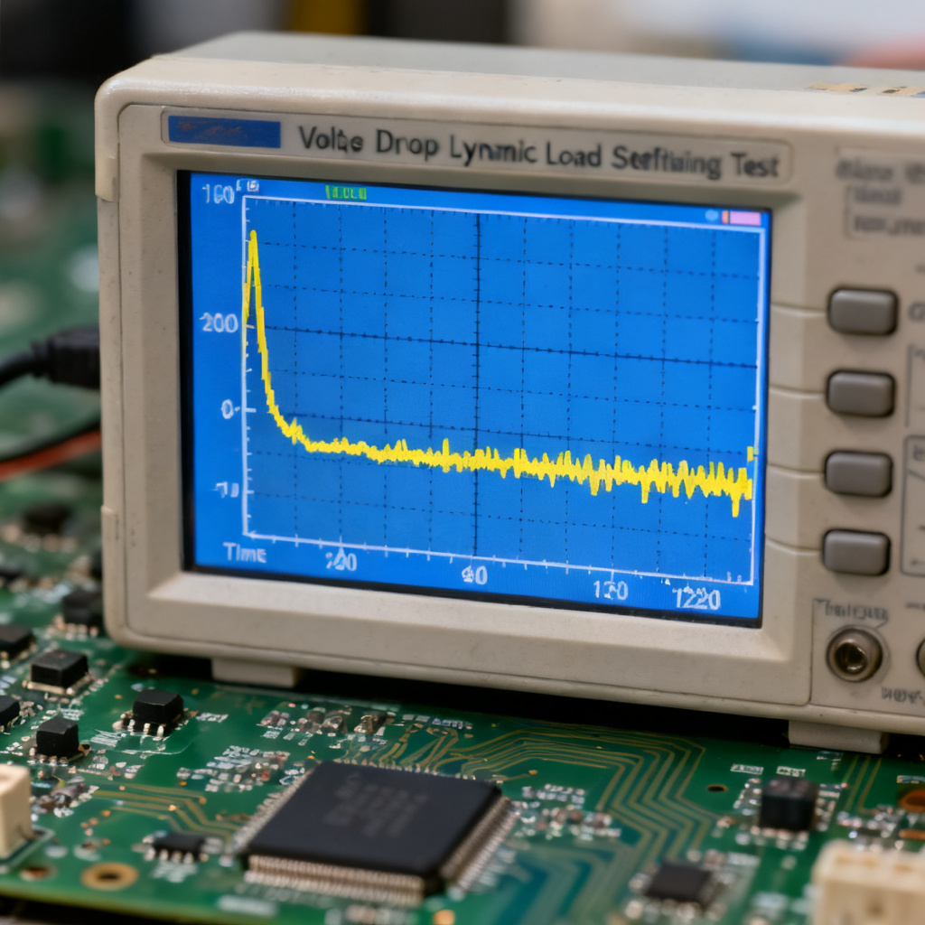
4.3 Measuring Under Dynamic Load Conditions
Inject 1–10 A load step at 1 kHz. Capture voltage droop and settling time. For high-speed PCBs, droop <5% and settling <10 µs.
5. Common Pitfalls and How to Avoid Them
| Pitfall | Consequence | Solution |
|---|---|---|
| Long ground lead | Adds 20–30 mV noise at 100 MHz | Use ground spring or coaxial tip |
| Probing at connector | Measures PCB trace impedance noise | Probe at load capacitor |
| Using 1× probe without bandwidth limit | Aliases high-frequency noise | Use 10× probe or bandwidth limit |
| AC coupling not enabled | Cannot see small ripple (DC offset) | Always use AC coupling |
| No DC blocking | Damages oscilloscope input | Use DC block or 10× probe |
| Measuring without load | Optimistic results | Measure under actual load |
6. Interpreting Results for PCB Design and Production
6.1 Acceptable Limits
Ripple: <10 mVpp for high-speed digital (DDR4, PCIe Gen 4); <5 mVpp for RF/analog. Noise: <20 mVpp for general digital; <10 mVpp for sensitive analog. Transient response: <5% voltage droop for 1 A step; settling <10 µs.
6.2 When to Redesign
For power integrity PCB design troubleshooting: If ripple exceeds 1% of rail voltage, add LC filter or ferrite bead. If noise peaks correlate with clock frequencies, review PCB layout (ground plane, decoupling capacitors). If transient response is poor, increase output capacitance or reduce ESR.
6.3 Documentation for Clients
Provide oscilloscope screenshots with measurement cursors (Vpp, RMS, frequency). Include FFT plots for spectral content. Note measurement conditions: probe type, bandwidth limit, load current, temperature.
7. Recommended Equipment for B2B PCB Validation
For high-speed PCB production: Oscilloscope: Keysight Infiniium S-Series (1 GHz, 10-bit), Tektronix MSO64 (6 GHz, 12-bit), R&S RTO2000 (2 GHz). Probes: Passive Tektronix TPP1000 (1 GHz); Active Keysight N2796A (1.5 GHz, differential). Accessories: 50 Ω SMA cables, DC blocks (Mini-Circuits BLK-89-S+), ground springs.
FAQ: Power Rail Ripple and Noise Measurement
What is the difference between power rail ripple and noise?
Ripple is periodic, low-frequency (50–100 kHz) from switching regulators. Noise is high-frequency, random (>100 MHz) from digital switching or crosstalk. Both affect power rail ripple and noise measurements.
Why is AC coupling recommended for measuring power rail ripple and noise?
AC coupling blocks the DC offset, allowing the oscilloscope to amplify small ripple and noise signals. This is critical for accurate power rail ripple and noise analysis.
What bandwidth is needed to measure power rail ripple and noise?
For ripple (100 kHz), 20 MHz bandwidth is sufficient. For high-frequency noise, use 1 GHz or higher. The bandwidth should be at least 5× the highest frequency of interest.
How do I avoid noise from the ground lead when measuring power rail ripple and noise?
Use a short ground spring or coaxial tip adapter. A long ground lead acts as an antenna, adding 20–30 mV noise at 100 MHz, corrupting power rail ripple and noise results.
What is the acceptable ripple level for high-speed PCBs?
For high-speed digital (DDR4, PCIe Gen 4), target <10 mVpp. For RF/analog, target <5 mVpp. This ensures power rail ripple and noise does not degrade signal integrity.
Conclusion
Measuring power rail ripple and noise is a competitive advantage in high-speed PCB manufacturing. By following these techniques, you ensure boards meet strict specifications for jitter, EMI, and signal fidelity. For B2B buyers, request a power integrity test report with every prototype or production batch.
Call to Action: Need expert PCB fabrication with guaranteed power integrity? Contact our engineering team for a free consultation on your high-speed design requirements.